Method and system for determining poses of semi-specular objects

Active Publication Date: 2009-12-03
MITSUBISHI ELECTRIC RES LAB INC
View PDF4 Cites 49 Cited by
  • Summary
  • Abstract
  • Description
  • Claims
  • Application Information

AI Technical Summary

Benefits of technology

[0017]Thus, both the scanner and the camera produce lower-quality information on semi-specular objects than on diffuse-surface objects. However, the method combines the 3D data and the 2D silhoue

Problems solved by technology

These techniques degrade as the surface becomes less diffuse and more specular, because the above assumptions are no longer true.
This is undesirable for many applications.
For example, it is difficult to determine a reliable pose of an object when the sensed features are sparse.
The problem can be ameliorated by moving the camera or the identifying features relative to the surface, but this increases the complexity of the system and is time-consuming.
This is because tech

Method used


Image

  • Method and system for determining poses of semi-specular objects
  • Method and system for determining poses of semi-specular objects
  • Method and system for determining poses of semi-specular objects

Examples


Example

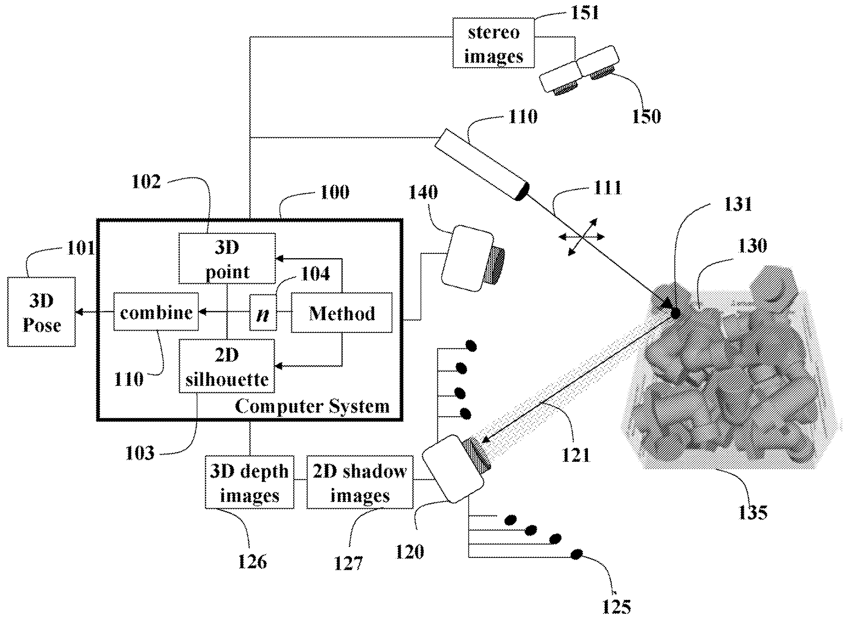
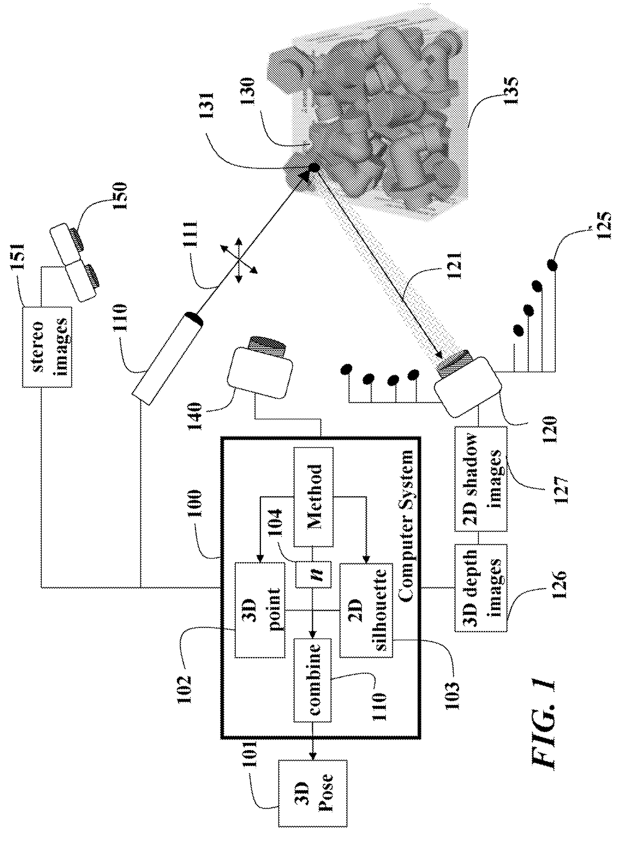
[0022]FIG. 1 shows a system and method 100 for determining a 3D pose 101 of an object 130 that includes semi-specular surfaces according to an embodiment of our invention. The 3D pose as defined herein means the 3D location and the 3D orientation of the object.

[0023]The system includes a hybrid sensor including a laser scanner 110 and a camera 120. The laser scanner 110 emits a laser beam 111 in a pattern 112 that can be used to determine 3D range data in a set of coded images 326 acquired by the camera 120. The pattern can use Gray-codes so that the pattern at each point on the surface of the object is unique. Thus, the method determines 3D coordinate data at each point on the surface from the set of coded images 126.

[0024]The camera also 120 acquires light 121 reflected by the object. The camera includes multiple flash units 125, e.g., LEDs, arranged at different locations, e.g., in an octagon or circular pattern, around the camera. The LEDs are bright point light sources that cas...


PUM


Abstract

A camera acquires a set of coded images and a set of flash images of a semi-specular object. The coded images are acquired while scanning the object with a laser beam pattern, and the flash images are acquired while illuminating the object with a set of light sources at different locations near the camera, there being one flash image for each light source. 3D coordinates of points on the surface of the object are determined from the set of coded images, and 2D silhouettes of the object are determined from shadows cast in the set of flash images. Surface normals are obtained for the 3D points from photometric stereo on the set of flash images. The 3D coordinates, 2D silhouettes and surface normals are compared with a known 3D model of the object to determine the pose of the object.

Description

FIELD OF THE INVENTION[0001]The invention relates generally to computer vision, and more particularly to determining poses of semi-specular objects.BACKGROUND OF THE INVENTION[0002]Sensors that acquire 3D data are useful for many applications. For example, a system for automated ‘bin-picking’ in a factory can acquire 3D data of a bin containing multiple instances of the same object, and compare the 3D data with a known 3D model of the object, in order to determine the poses of objects in the bin. Then, a robot arm can be directed to retrieve a selected one of the objects. The pose of an object is its 3D location and 3D orientation at the location. One set of vision-based techniques for sensing 3D data assumes that the objects have non-specular surfaces, such as matte surfaces.[0003]Another type of sensor determines the silhouette of the object, and compares the silhouette with the known 3D model of the object, in order to determine pose. One set of techniques for determining the sil...

Claims


Application Information

Patent Timeline
IPC IPC(8): G06K9/00
CPCG06T7/0057G06T2207/10152G06T7/0085G06T7/0073G06T7/13G06T7/521G06T7/586
Inventor BEARDSLEY, PAUL A.BAECHER, MORITZ
Owner MITSUBISHI ELECTRIC RES LAB INC
Why Eureka
Try Eureka