Malfunction diagnosis system and malfunction diagnosis method for electric vehicle on-board device

a technology for malfunction diagnosis and electric vehicles, which is applied in the direction of electric devices, battery/fuel cell control arrangements, instruments, etc., can solve the problems of excessively reducing the charge in the secondary battery, and affecting the accuracy of diagnosis results

Active Publication Date: 2009-12-03
TOYOTA JIDOSHA KK
View PDF4 Cites 34 Cited by
  • Summary
  • Abstract
  • Description
  • Claims
  • Application Information

AI Technical Summary

Benefits of technology

[0011]The present invention provides a malfunction diagnosis system for an electric vehicle on-board device which determines whether a malfunction has occurred in the on-board device with high accuracy and prevents the amount of charge in an electric storage section, which supplies electric power to the malfunction diagnosis device, from becoming excessively low, and a malfunction diagnosis method therefor.

Problems solved by technology

If malfunction diagnosis is performed on the evaporative emission control device in an electric vehicle when the vehicle is not driven as described above, the diagnosis device is supplied with electric power from a low-voltage secondary battery for auxiliary devices but the electric power which can be used to operate the diagnosis device is limited because the low-voltage secondary battery is not charged from a power generator.
Thus, if malfunction diagnosis is made frequently or for prolonged periods when the diagnosis device is used, the amount of charge in the secondary battery may be excessively decreased, that is, a dead battery may occur.

Method used


Image

  • Malfunction diagnosis system and malfunction diagnosis method for electric vehicle on-board device
  • Malfunction diagnosis system and malfunction diagnosis method for electric vehicle on-board device
  • Malfunction diagnosis system and malfunction diagnosis method for electric vehicle on-board device

Examples


Embodiment Construction

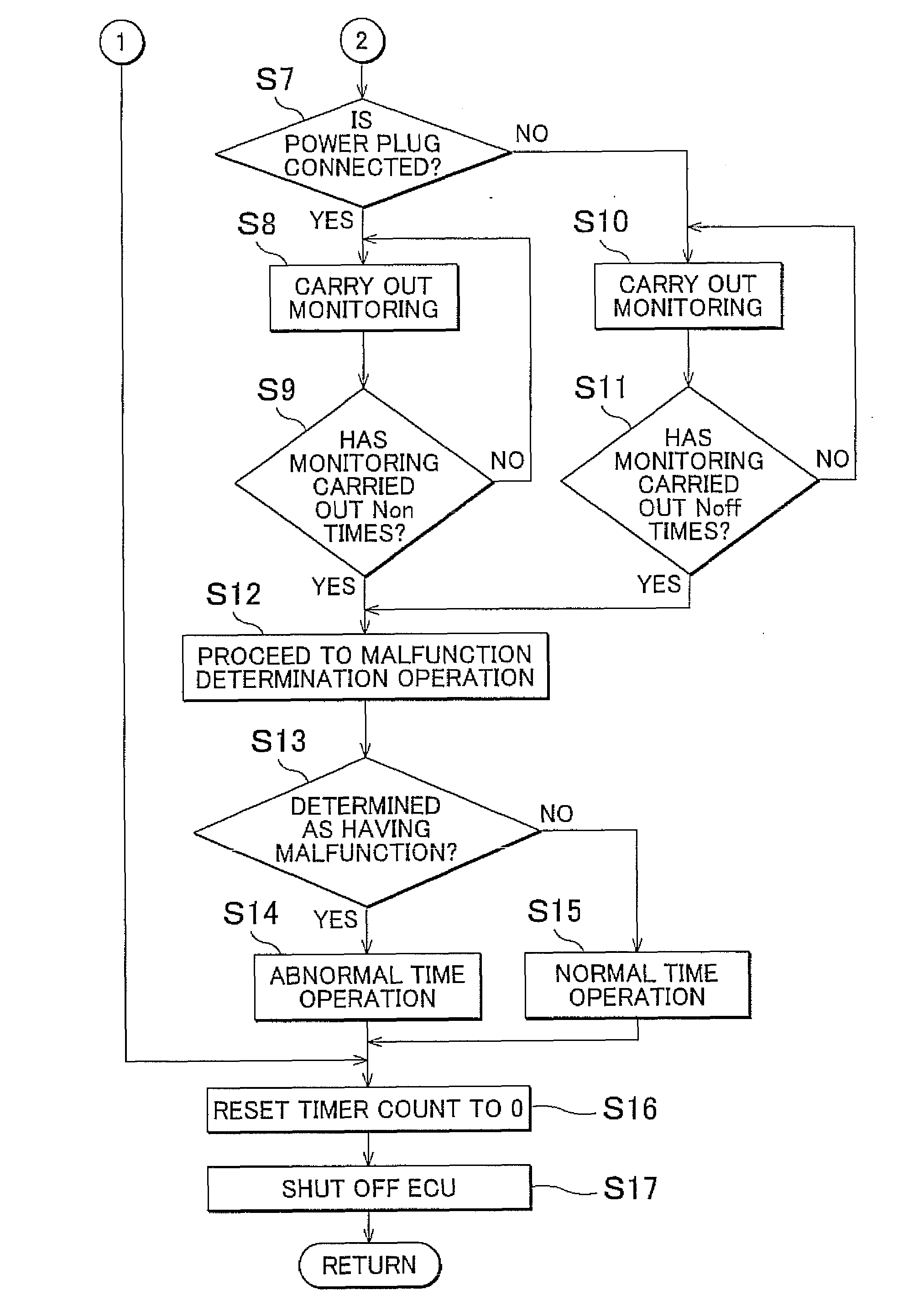
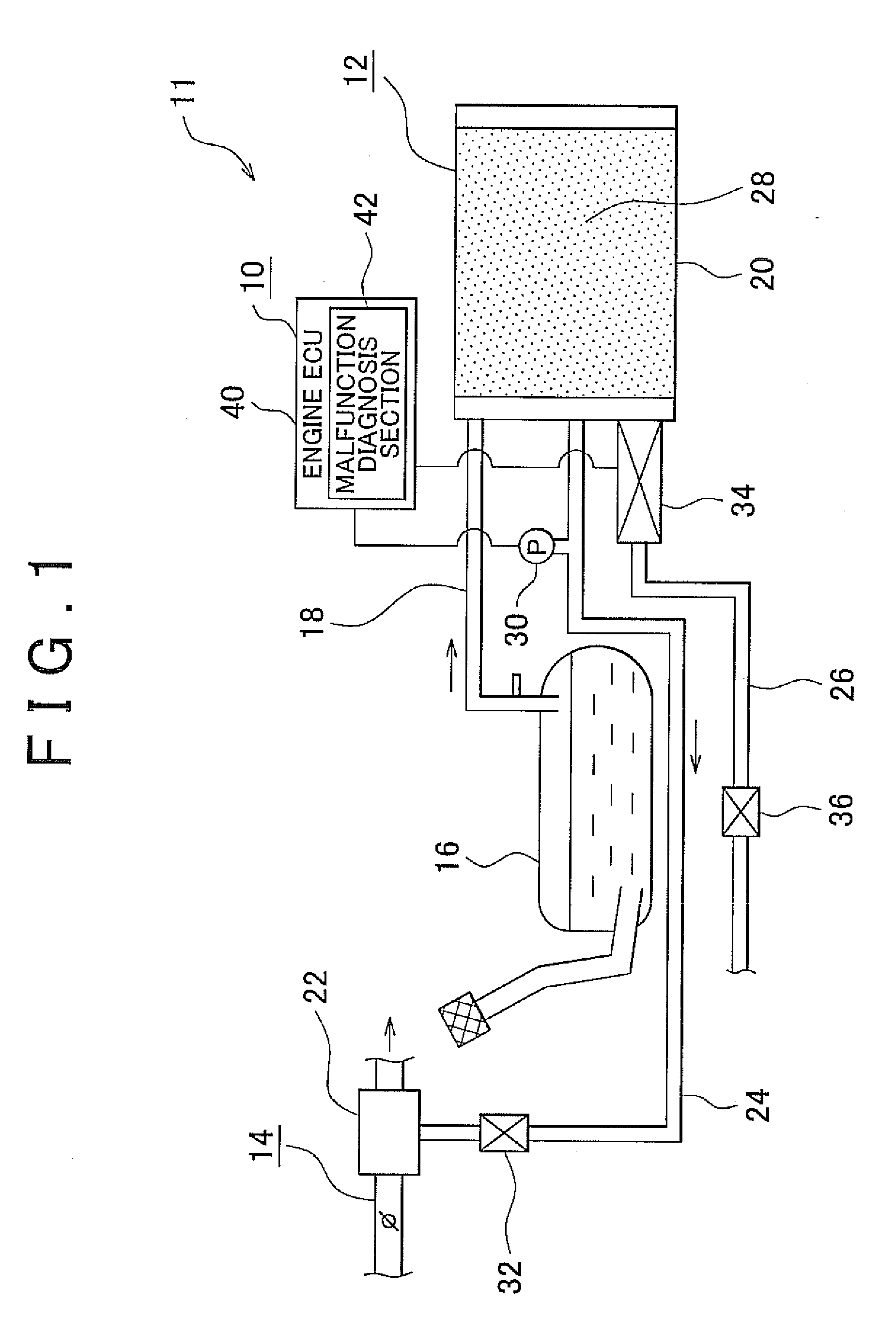
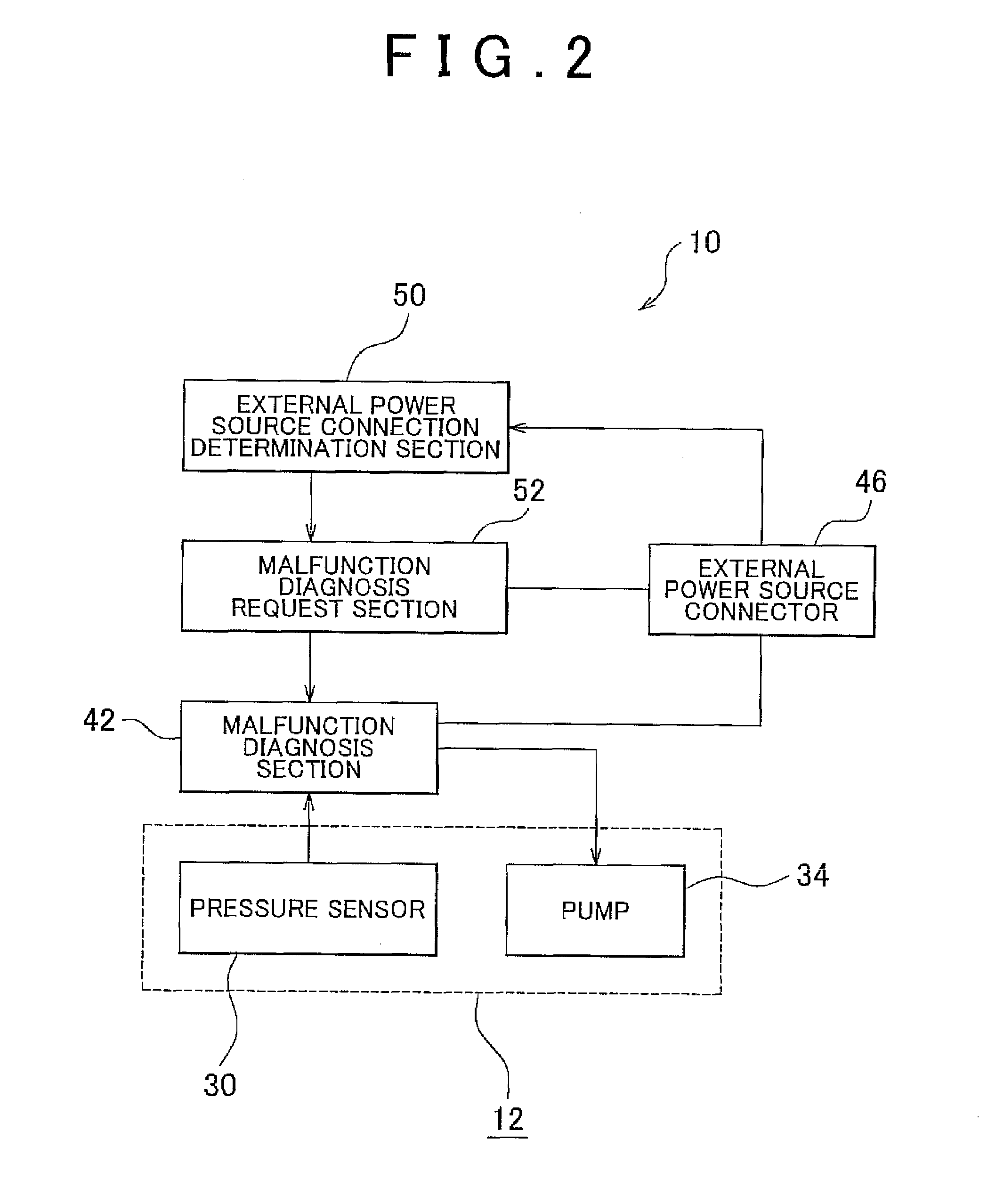
[0022]An embodiment of the present invention will be described below in detail with reference to the drawings. FIG. 1 to FIG. 5B illustrate an example embodiment of the present invention. FIG. 1 is a schematic view of an evaporative emission control device for which a malfunction diagnosis system for an electric vehicle performs the malfunction diagnosis. FIG. 2 is a block diagram that illustrates a basic configuration of the malfunction diagnosis system of the embodiment. FIG. 3 is a block circuit diagram that illustrates the malfunction diagnosis system of this embodiment in more detail than FIG. 2. FIG. 4 is a configuration diagram that illustrates a battery ECU and an engine ECU taken out of FIG. 3 in more detail. FIG. 5A and FIG. 5B is a flowchart that illustrates a malfunction diagnosis method for the electric vehicle on-board device of the embodiment.

[0023]As shown in FIG. 1, the on-board device for which a malfunction diagnosis is performed by a malfunction diagnosis system ...


PUM


Abstract

A malfunction diagnosis system includes: a malfunction diagnosis section that performs a malfunction diagnosis for an on-board device of an electric vehicle when supplied with electric power from either an electric storage section or an external power source; a malfunction diagnosis request section that requests the malfunction diagnosis section to carry out malfunction diagnosis; an external power source connector that supplies electric power from the external power source; and an external power source connection determination section that determines whether the external power source connector is connected to the external power source. The malfunction diagnosis request section changes at least either the number of times that the malfunction diagnosis section is requested to carry out malfunction diagnosis or the period of time the malfunction diagnosis section is requested to carry out malfunction diagnosis depending whether the external power source connector is connected to the external power source.

Description

INCORPORATION BY REFERENCE[0001]The disclosure of Japanese Patent Application No. 2008-144509 filed on Jun. 2, 2008 including the specification, drawings and abstract is incorporated herein by reference in its entirety.BACKGROUND OF THE INVENTION[0002]1. Field of the Invention[0003]The present invention relates to a malfunction diagnosis system for an electric vehicle on-board device that includes a malfunction diagnosis section that diagnoses whether the electric vehicle on-board device has a malfunction when supplied with electric power from at least one of an electric storage section or an external power source, and a malfunction diagnosis method therefor.[0004]2. Description of the Related Art[0005]In general, it is contemplated diagnosing whether a malfunction has occurred in a device mounted on an electric vehicle equipped with a traction motor, such as an electric car or a hybrid vehicle, is performed after the ignition switch has been turned off. One example of such a device...

Claims


Application Information

Patent Timeline
Patent Type & Authority Applications(United States)
IPC IPC(8): G06F7/00B60W20/00B60L50/10
CPCB60K6/28B60L3/0046B60K15/03504B60L58/14B60L58/26Y02T10/70
Inventor MATSUMOTO, TAKUYA
Owner TOYOTA JIDOSHA KK
Why Eureka
Try Eureka