
Execution Unit With Inline Pseudorandom Number Generator

a pseudorandom number and execution unit technology, applied in the field of data processing, can solve the problems of slow function, inefficient execution of certain algorithms in a conventional execution unit, and inability to produce good random numbers in conventional hardwar

Inactive Publication Date: 2009-12-03
IBM CORP
View PDF5 Cites 43 Cited by
  • Summary
  • Abstract
  • Description
  • Claims
  • Application Information

AI Technical Summary

Benefits of technology

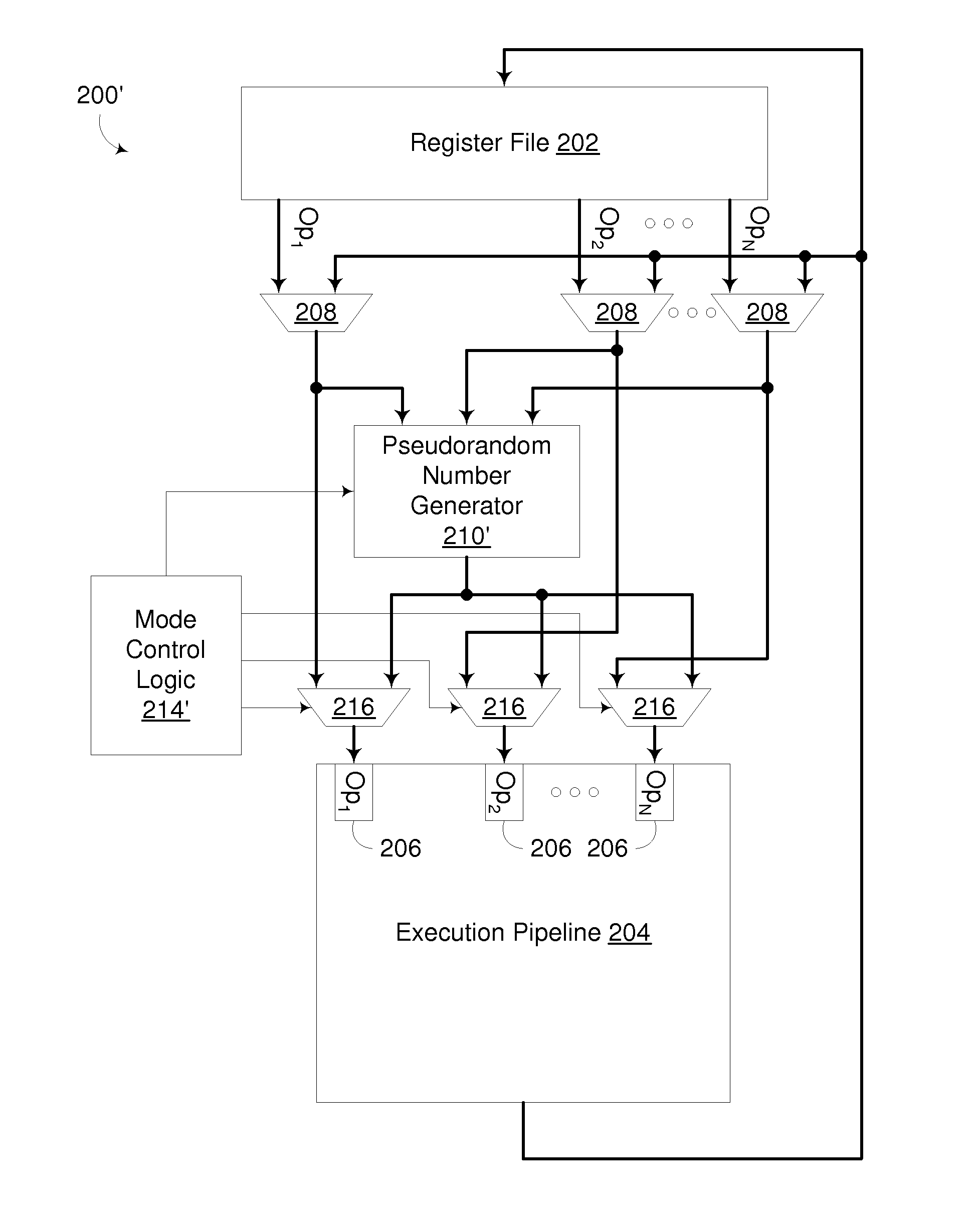
[0015]The invention addresses these and other problems associated with the prior art by coupling a hardware-based pseudorandom number generator (PRNG) to an execution unit in such a manner that pseudorandom numbers generated by the PRNG may be selectively output to the execution unit for use as an operand during the execution of instructions by the execution unit. In some embodiments, for example, a PRNG is coupled to an input of an operand multiplexer that outputs to an operand input of an execution unit so that operands provided by instructions supplied to the execution unit are selectively overridden with...

Problems solved by technology

It has been found, however, that while this configuration is highly desirable for a significant amount of code, there are certain algorithms that are inefficient to execute in a conventional execution unit.
The need for such randomness has traditionally been a major drawback to using procedural textures due to the fact that producing good random numbers in conventional hardware is typically a very computationally intensive operation.
With conventional execution units, it would take at least 9 full passes through an arithmetic pipeline to perform this function each time it is called (which would usually be multiple times per pixel), with many of those passes dependent on a previous pass, making this a very slow function.
However, in many conventional execution units, the generation of pseudorandom numbers adversely impacts performance due to the highly dependent nature of known algorithms.

Method used


Image

  • Execution Unit With Inline Pseudorandom Number Generator
  • Execution Unit With Inline Pseudorandom Number Generator
  • Execution Unit With Inline Pseudorandom Number Generator

Examples


Embodiment Construction

[0026]Embodiments consistent with the invention utilize an inline pseudorandom number generator (PRNG) in an execution unit to enable pseudorandom numbers generated by the PRNG to be selectively output to the execution unit for use as an operand during the execution of instructions by the execution unit. In many embodiments, providing pseudorandom numbers as operands for an execution unit in the manner described herein avoids dependent instruction stalls and long latency pseudorandom functions typically associated with the generation and use of pseudorandom numbers in conventional execution units.

Hardware and Software Environment

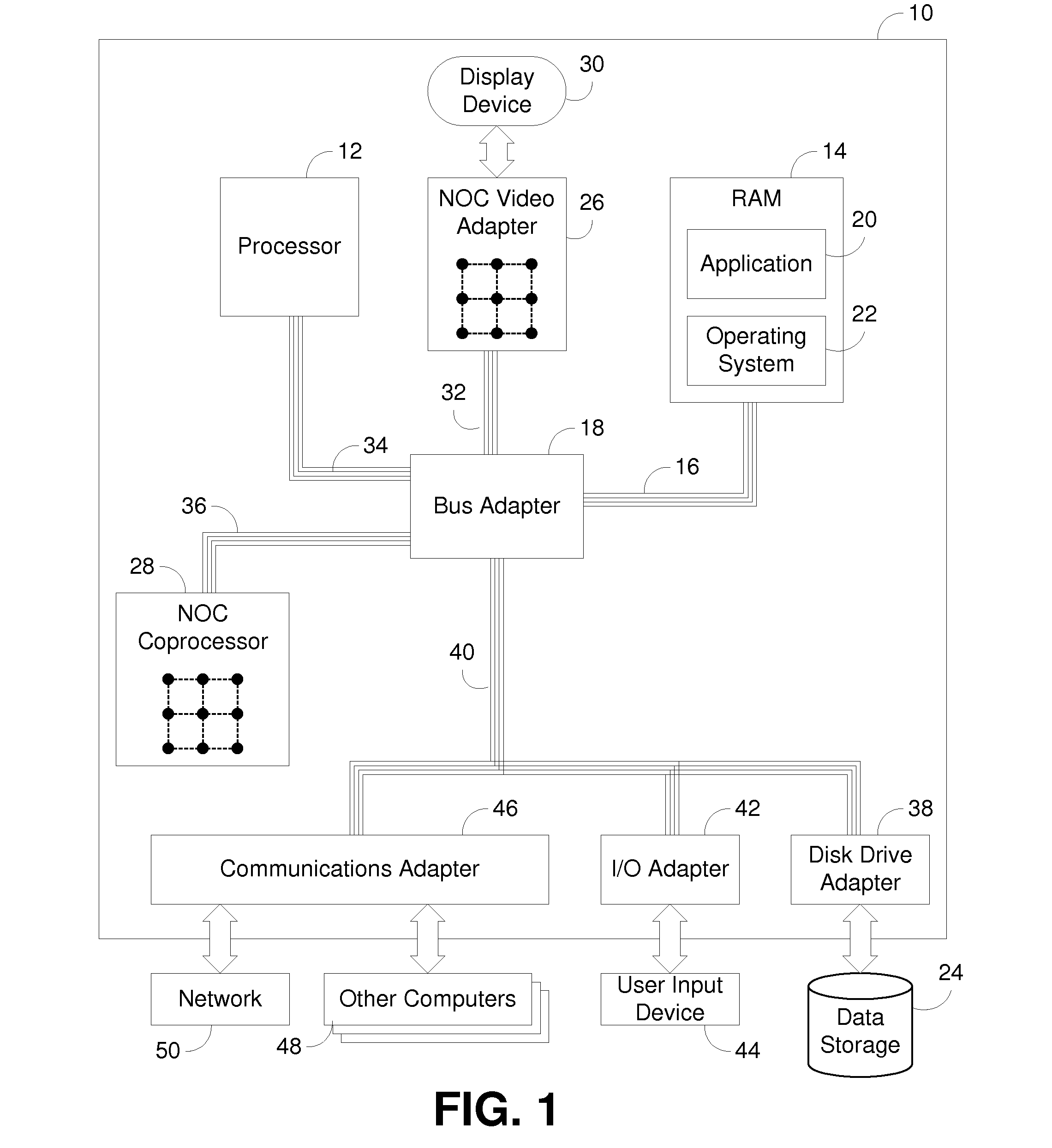
[0027]Now turning to the drawings, wherein like numbers denote like parts throughout the several views, FIG. 1 illustrates exemplary automated computing machinery including an exemplary computer 10 useful in data processing consistent with embodiments of the present invention. Computer 10 of FIG. 1 includes at least one computer processor 12 or ‘CPU’ as well...


PUM


Abstract

A circuit arrangement and method couple a hardware-based pseudorandom number generator (PRNG) to an execution unit in such a manner that pseudorandom numbers generated by the PRNG may be selectively output to the execution unit for use as an operand during the execution of instructions by the execution unit. A PRNG may be coupled to an input of an operand multiplexer that outputs to an operand input of an execution unit so that operands provided by instructions supplied to the execution unit are selectively overridden with pseudorandom numbers generated by the PRNG. Furthermore, overridden operands provided by instructions supplied to the execution unit may be used as seed values for the PRNG. In many instances, an instruction executed by an execution unit may be able to perform an arithmetic operation using both an operand specified by the instruction and a pseudorandom number generated by the PRNG during the execution of the instruction, so that the generation of the pseudorandom number and the performance of the arithmetic operation occur during a single pass of an execution unit.

Description

FIELD OF THE INVENTION[0001]The invention is generally related to data processing, and in particular to processor architectures and execution units incorporated therein.BACKGROUND OF THE INVENTION[0002]As semiconductor technology continues to inch closer to practical limitations in terms of increases in clock speed, architects are increasingly focusing on parallelism in processor architectures to obtain performance improvements. At the chip level, multiple processor cores are often disposed on the same chip, functioning in much the same manner as separate processor chips, or to some extent, as completely separate computers. In addition, even within cores, parallelism is employed through the use of multiple execution units that are specialized to handle certain types of operations. Pipelining is also employed in many instances so that certain operations that may take multiple clock cycles to perform are broken up into stages, enabling other operations to be started prior to completio...

Claims


Application Information

Patent Timeline
IPC IPC(8): G06F9/302G06F7/58
CPCG06F9/30181G06F9/30014G06F9/3851G06F9/3888
Inventor MUFF, ADAM JAMESTUBBS, MATTHEW RAY
Owner IBM CORP
Learn More