Control method for mig/mag-welding and welding equipment applying this method

a control method and welding equipment technology, applied in welding equipment, arc welding equipment, manufacturing tools, etc., can solve problems such as troublesome uncertainty, inability to test synergy lines anymore, and significant weld spatter and weld smoke, and achieve good effect on welding tolerance, increase the security of a proper repetition accuracy during welding with materials from different suppliers and different manufacturing batches, and good

Active Publication Date: 2009-12-10
ESAB AB
View PDF17 Cites 11 Cited by
  • Summary
  • Abstract
  • Description
  • Claims
  • Application Information

AI Technical Summary

Benefits of technology

[0012]The introduction of a regulator for maintaining the percentage of the short-circuiting time of the period time constant at the desired set value, where the period time is the sum of the short-circuiting time and the arc time has had a particular and surprisingly good effect on the tolerance of the welding towards different external influencing factors, such as distance keeping between a contact tip and the workpiece. Furthermore, a machine of this kind is operable for a large variety of weld electrode dimensions and materials. Likewise, a proper tolerance towards different shielding gas compositions is achieved. The need of tested synergy lines is to a large extent not needed any longer, and thus the security of a proper repetition accuracy during welding with materials from different suppliers and from different manufacturing batches is increased.

Problems solved by technology

The result is an unstable arc with significant weld spatter and weld smoke.
A well-known problem is that a suitable reference value for the voltage for each electrode speed is dependent on such factors as electrode material, electrode dimension and shielding gas type.
In addition, the material quality may vary between different deliveries and lead to the fact that previously tested synergy lines do not function any longer.
Also, this leads to problems in having a predetermined quantity of synergy lines suitable for all weld cases.
Obviously, this leads to a troublesome uncertainty when welding a new batch.
Another problem is that the technique up to now does not give a uniform weld result at varying distance between the contact tip in the weld torch and the workpiece, such as during passage of areas of tack welding and corners.

Method used


Image

  • Control method for mig/mag-welding and welding equipment applying this method
  • Control method for mig/mag-welding and welding equipment applying this method

Examples


Embodiment Construction

[0021]In the following some possible embodiments of the invention will be described. Further embodiments may of course be possible within the scope of the claims.

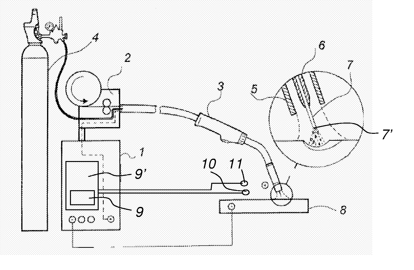
[0022]FIG. 1 discloses welding equipment for MIG / MAG welding with the presence of short-circuiting droplets between an end 7′ of an electrode 7 and a workpiece 8. The welding equipment disclosed comprises a welding machine 1 having a current source adapted to supply welding energy, or melting power, to the electrode 7. Preferably the current source comprises an inverter power supply. An electrode feeder 2 is provided on the welding machine 1. The electrode feeder 2 is adapted to feed the electrode 7 to a welding torch 3. The welding torch 3 is connected to the electrode feeder 2, the welding machine 1 and a gas container 4 via a welding cable. The welding torch 3 comprises a gas cup 5 and a contact tube 6 through which the electrode 7 is fed to a position in the proximity of the workpiece 8. Welding gas is supplied from the...


PUM

PropertyMeasurementUnit
short-circuiting aaaaaaaaaa
melting efficiencyaaaaaaaaaa
short-circuiting timeaaaaaaaaaa

Abstract

The present invention refers to a control method and welding equipment for MIG / MAG-welding with presence of short-circuiting droplets between an electrode end and a workpiece. The method comprises establishment of a short-circuiting time, establishment of an arc time, and controlling the energy supplied to the electrode. The energy supply is controlled in such a way that the energy supply is increased if a measured short-circuiting time of a total period time, where the period time is the sum of the short-circuiting time and the arc time, exceeds a defined adjustable set value and decreases if said short-circuiting percentage goes below said set value.

Description

FIELD OF THE INVENTION[0001]The present invention refers generally to the control of a short arc welding process in a welding equipment adapted for MIG / MAG-welding.BACKGROUND[0002]In gas metal arc welding with melting, continuously fed electrode, frequently named MIG / MAG-welding, the workpiece is heated primarily by the arc. The electrode is heated, partly by the power supplied when the weld current flows through the electrode stick out i.e. the free electrode end between the contact tip, where the current transfer to the electrode takes place, and the arc, partly by the arc itself. The basic control of the welding process aims at achieving an electrode melting speed which corresponds to the electrode feed speed. Further objects of the control may for instance be to influence the amount of heat transferred to the workpiece.[0003]MIG / MAG-welding takes place in one of three states. In short arc welding, the material transport from the electrode to the workpiece takes place through lar...

Claims


Application Information

Patent Timeline
Patent Type & Authority Applications(United States)
IPC IPC(8): B23K9/09
CPCB23K9/091B23K9/173B23K9/0953B23K9/06B23K9/0956
Inventor BERG, PER
Owner ESAB AB
Why Eureka
Try Eureka