Light amplification unit

Inactive Publication Date: 2009-12-10
LEVON LEIF ERIC TOBIAS
View PDF3 Cites 10 Cited by
  • Summary
  • Abstract
  • Description
  • Claims
  • Application Information

AI Technical Summary

Benefits of technology

[0023]Light Amplification units are so efficient that they emit light during overcast or rainy conditions much better than comparable prior art. The novelty of being more visible may well contribute to increased safety regarding stationary road reflectors or dynamic reflectors affixed to vehicles or pedestrians.
[0024]Additionally, Light Amplification Units may easily be combined with other internal ligh

Problems solved by technology

An enhanced light amplification unit is required that is not solely dependent on directional light per se, but may operate well under unf

Method used


Image

  • Light amplification unit
  • Light amplification unit
  • Light amplification unit

Examples


Example

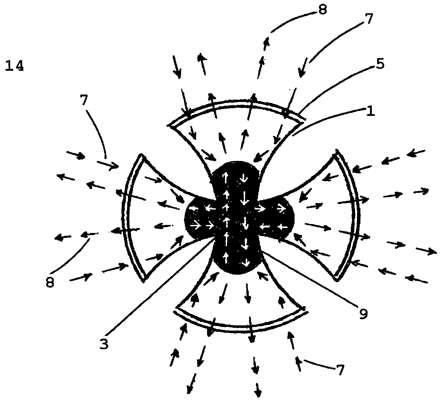
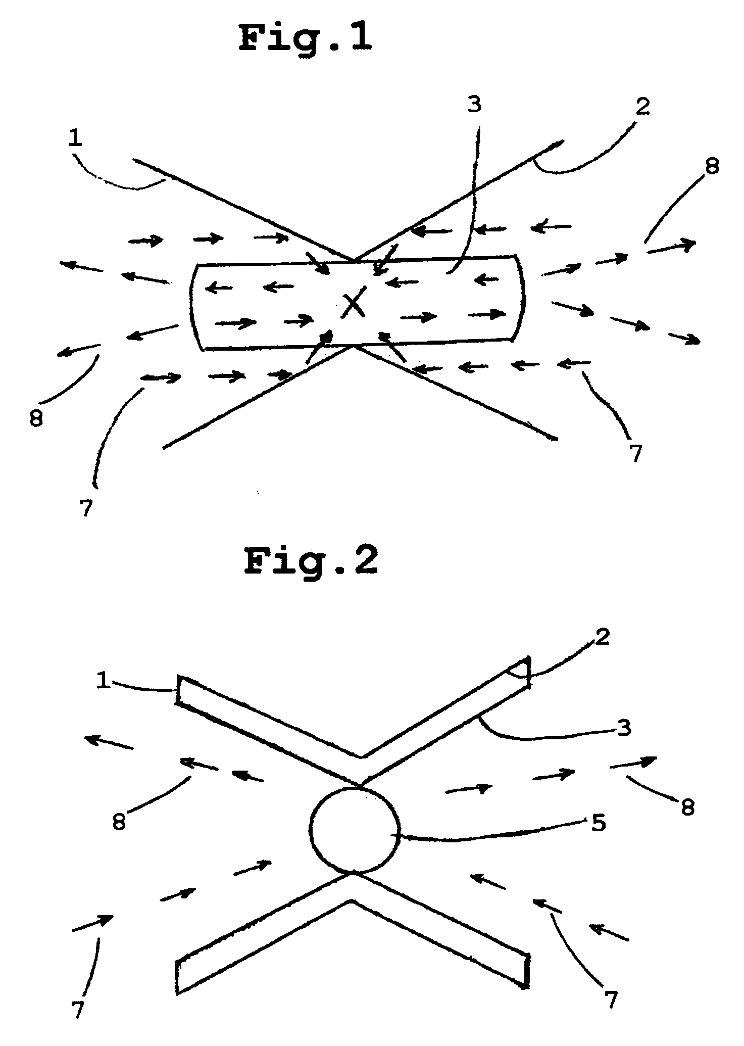
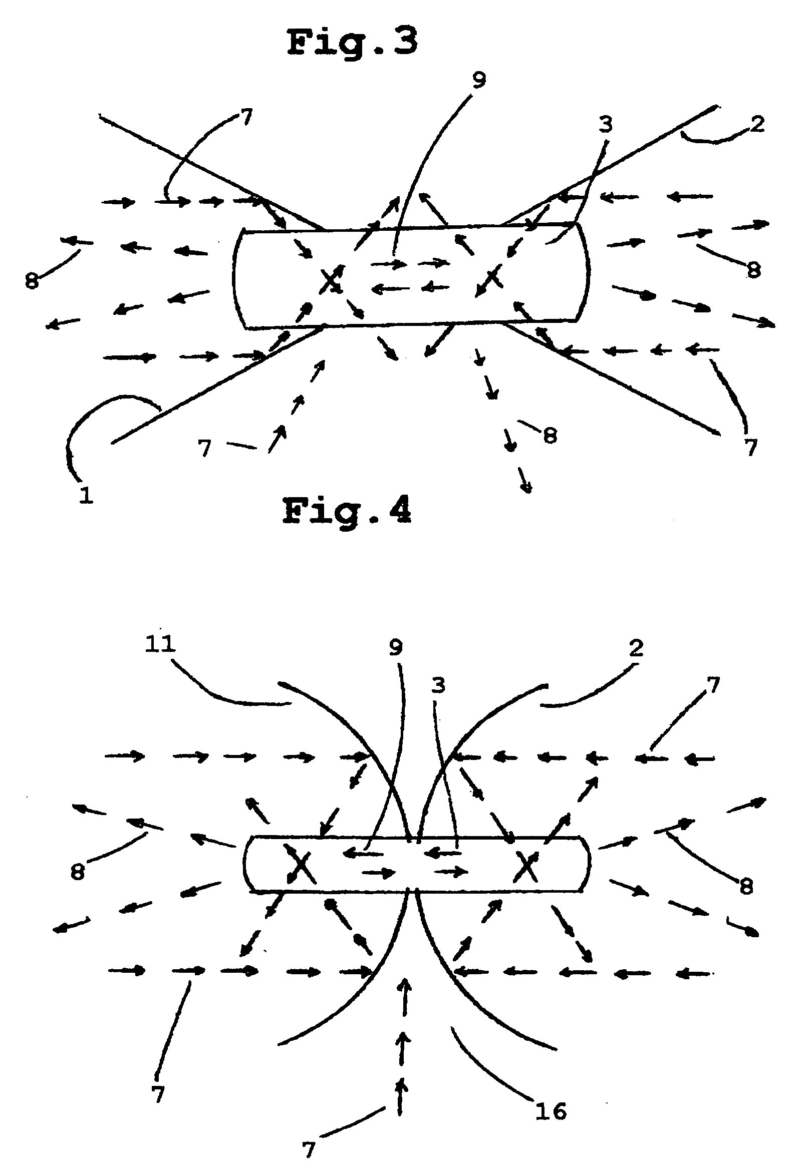
[0055]FIG. 1 Illustrates a preferred embodiment of a hyperbolically shaped Light Amplification Unit in cross section. Light 7 enters from either side of large apertures 6, and is internally reflected and directed toward optimally placed luminescent or fluorescent body member 3, extending from adjoining tapered zone, interconnecting conical sections 1 and 2 Electrons within luminescent or fluorescent material 3, become excited by radiant energy and release additional photons. Resultant light amplification occurs when light of short wavelength converts to more visible light of longer wavelength and is emitted 8 from either side of hyperbolic openings. Light may be further amplified and directed by surrounding lenses to exit and entry points.

[0056]FIG. 2 Illustrates a cross sectional variant of FIG. 1. A lens or prism 5, with or without luminescent proporties is internally housed between convergent aperture, seperating conic halves 1 an 2. Luminescent or fluorescent material 3 lines re...


PUM


Abstract

A general purpose energy saving light amplification unit suitable as a lantern, guide light, background light, safety light, ornament or decorative object, said unit adapted to harness external surrounding ambient light, or other remote energy sources from at least two directions, employing a plurality of reflector members to receive and concentrate energy in in order to luminesce or fluoresce an optimally placed mutually shared luminescent or fluorescent body member, lodged in a tapered or convergent section of a hyperbola or between at least two juxstaposed reflectors, stimulating photon and electron activity resulting in maximum amount of transmitted visible light from at least two directions, irrespective of receptive direction or angle of origin of light source.

Description

[0001]The present application for patent claims priority to patent applications: GB0810263.4; GB0813946.1; GB0901332.7; EP08445033 and EP09445010. EP09445012, U.S. Ser. No. 12 / 288,409, and U.S. Ser. No. 12 / 384,221, as well as UK design applications; 4010967, 4010968, 4010969, 4010970,FIELD OF INVENTION[0002]This invention relates to energy saving light amplification units powered by surrounding ambient light or distant energy sources.BACKGROUND[0003]Various methods are available to capture ambient natural light and enhance fluorescence and luminescence ability in fluorescent or luminescent material. Prior art does not optimally receive, collect, concentrate and direct diffuse surrounding ambient rays, but rather relies more on directional light indirectly projected unilaterally onto partial sections of luminscent material or surface areas, limiting exposure to radiant energy with resultant loss of efficiency.PRIOR ART[0004]GB2041506—shows a solar collection system fluorescing a body...

Claims


Application Information

Patent Timeline
IPC IPC(8): H01J65/00
CPCA41D27/085F21S11/00F21S19/00G09F19/02F21V7/04F21Y2101/02F21V7/0025F21Y2115/10
Inventor LEVON, LEIF ERIC TOBIAS
Owner LEVON LEIF ERIC TOBIAS
Why Eureka
Try Eureka