Electromagnetic subterranean imaging instrument

a subterranean imaging and electromagnetic technology, applied in the field of electromagnetic subterranean imaging instruments, can solve the problems of low signal remaining for analysis, low dynamic range, and easy absorbing of high frequency signals, and achieve the effect of high dynamic rang

Active Publication Date: 2009-12-10
LOPEZ JOHN A +4
View PDF13 Cites 15 Cited by
  • Summary
  • Abstract
  • Description
  • Claims
  • Application Information

AI Technical Summary

Benefits of technology

[0025]Another object of the present invention is to provide an instrument with high dynamic range and capable of sensing extremely tiny signals without saturation or loss of sensitivity so that meaningful readings of small differences indicative of subterranean details can be gathered and studied.
[0026]Another object of the present invention is to provide an instrument which can adjust power and / or frequency levels in real time to adjust for soil conductivity or other conditions which can result in more meaningful sensed data if adjusted.
[0027]Another object of the present invention is to provide an instrument which can send real time data to a remote location for analysis and / or manipulation or storage at a separate location via a remote data link.

Problems solved by technology

However, high frequency signals are readily absorbed by soil leaving little of the signal remaining for analysis.
If objects or features to be found are too deep, such high frequency systems have proven generally ineffective.
While this instrument is effective in imaging underground anomalies it suffers from numerous drawbacks.
The instrument is only portable in a very crude sense in that it can be picked up and hand carried.
The practical survey range of such an instrument is therefore limited.
Furthermore, its power levels are limited, such that only objects relatively close to the surface can be imaged with any degree of effectiveness.
Also, such instruments are prone to saturation in high soil conductance environments and other high noise environments.
Furthermore, coil antennas are susceptible to self-capacitance, especially when operated at high power levels, such that the coil antenna increases in self-capacitance as the power level is increased and little or no real net benefit is realized by merely increasing the power to the transmitter antenna.
Such difficulties, as well as high weight and bulk have kept the state of the art from advancing and limited the effectiveness of such subterranean imaging instruments.
The lack of portability and rates of data collection in prior art instruments have prevented effective utilization of subterranean imaging systems in the prior art for large subterranean area surveys.
In addition, prior art instruments have a great tendency to saturate in high conductivity soil conditions and lack sufficient sensitivity in low conductivity soil conditions.
Thus, small but significant values are not detected by such prior art instruments.

Method used


Image

  • Electromagnetic subterranean imaging instrument
  • Electromagnetic subterranean imaging instrument
  • Electromagnetic subterranean imaging instrument

Examples


first embodiment

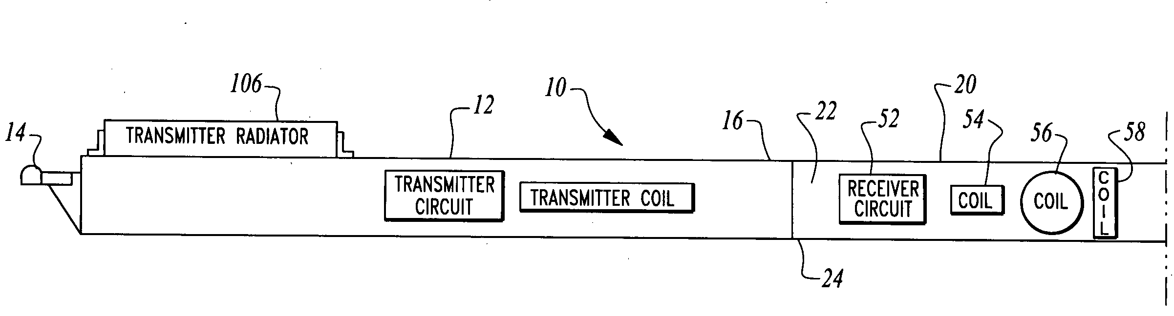
[0091]The receiver assemblies 50 are preferably mounted upon the carriers 30 within one of the tube segments 20. The receiver assemblies 50 each include a receiver circuit 52 and at least one coil antenna defining a receiver coil 54. Three subembodiments are illustrated in FIGS. 11-16 for the receiver assemblies 50. In a first embodiment shown in FIGS. 11 and 12, the receiver assembly 50′ has a receiver circuit 52 coupled to a single receiver coil antenna 54 oriented about axis A perpendicular to a plane of the receiver circuit 52, which is typically provided on a printed circuit board and includes appropriate electronics mounted thereon for operation of the receiver circuit 52.

second embodiment

[0092]In a second embodiment, shown in FIGS. 13 and 14, the receiver assembly 50″ includes a receiver circuit 52 and a pair of coil antennas including a receiver coil antenna 54 oriented relative to axis A and a receiver coil antenna 56 oriented about axis B perpendicular to axis A and generally coplanar with a plane of the printed circuit board for the receiver circuit 52.

[0093]In a third embodiment (FIGS. 15 and 16) corresponding with the preferred embodiment of this invention (FIG. 8), the receiver assembly 50 includes a receiver circuit 52 and three coil antennas in the form of receiver coil antenna 54, receiver coil antenna 56 and receiver coil antenna 58, oriented about axis A, axis B and axis C, respectively. Each of these coil antennas 54, 56, 58 are oriented mutually perpendicular to each other in this embodiment of FIGS. 15 and 16.

[0094]For each of these embodiments for the receiver assemblies 50, a power line 32 and signal line 34 are coupled to the receiver circuit 52 an...


PUM


Abstract

The instrument utilizes at least one electromagnetic signal transmitter and at least one electromagnetic signal receiver with the receiver detecting a receiver signal responsive to the transmitter signal and indicative of subterranean details adjacent to the instrument. The instrument is attachable to a tow vehicle for transport and includes a GPS antenna and tags data gathered by the instrument with GPS position information. The instrument is formed- in modular sections which can be removably attached for collapsing into a smaller space and to allow for flexible configuration of the instrument in various different ways. A wheeled carriage is provided to carry the instrument over the ground. Antennas for the transmitter and receiver, as well as circuitry and cooling systems are all provided to supply the instrument with high resolution and a clear signal indicative of the position and characteristics of subterranean details of interest.

Description

FIELD OF THE INVENTION[0001]The following invention relates to instruments for use in imaging subterranean regions through utilization of an electromagnetic signal transmitter and receiver. More particularly, this invention relates to such imaging instruments which are ground mobile and which can operate while in motion and be configured in a variety of different ways while exhibiting a high degree of sensitivity. Data from such an instrument may be tagged, such as with GPS position data to allow the instruments to survey a defined subterranean space.BACKGROUND OF THE INVENTION[0002]The ability of electromagnetic fields to extend to varying degrees through solid material makes possible the use of electromagnetic field generators and sensors for imaging of subterranean spaces. Instruments have been developed over time to take advantage of this ability of electromagnetic fields to penetrate solid objects. For instance, classic metal detectors generate an electromagnetic field and sens...

Claims


Application Information

Patent Timeline
Patent Type & Authority Applications(United States)
IPC IPC(8): G01V3/17
CPCG01V3/15
Inventor LOPEZ, JOHN A.CYLIAX, INGOCAISSE, MICHAELWORD, DARRELL R.SORENSON, ROD
Owner LOPEZ JOHN A
Why Eureka
Try Eureka