Impedance matched guided wave radar level gauge system

a radar level gauge and guided wave technology, applied in the direction of antennas, liquid/fluent solid measurements, reradiation, etc., can solve the problems of reducing the maximum measurable distance (minimum measurable filling level), difficult to determine the filling level, and not suitable for tank installations, etc., to improve the filling level determination, improve the accuracy of measurement, and improve the effect of impedance matching

Active Publication Date: 2009-12-10
ROSEMOUNT TANK RADAR
View PDF13 Cites 57 Cited by
  • Summary
  • Abstract
  • Description
  • Claims
  • Application Information

AI Technical Summary

Benefits of technology

[0023]The present invention is based on the realization that the impedance transition between the probe-transceiver connection and the probe can be made considerably less abrupt by arranging a tapered impedance matching device to extend along a portion of the probe inside the tank. The present inventor has further realized that such an impedance matching device can be made sufficiently compact, in terms of its extension in a direction perpendicular to the probe, that the impedance matching device (possibly pre-attached to the probe) can be inserted through even a relatively narrow through-hole provided in a wall (typically the roof) of the tank.
[0024]Hereby, an improved impedance matching, and hence an improved filling level determination in the near-zone (close to the tank ceiling) and an increased measurement range can be achieved also for applications where the through-hole in the tank wall is relatively small, such as having a diameter of only 1″-2″.
[0026]An impedance matching device that extends a distance corresponding to at least a quarter of the wavelength of the transmitted signal can provide impedance matching that may be sufficient for many applications. To achieve a more wideband impedance transition, the impedance transition device may advantageously extend a longer distance along the portion of the probe inside the tank, such as a distance corresponding to at least half the wavelength of the transmitted signal, or, for providing impedance matching across an even wider bandwidth, a distance corresponding to at least the wavelength of the transmitted signal.
[0035]Alternatively, the extension perpendicular to the probe of the impedance matching device may decrease stepwise along the portion of the probe inside the tank.
[0039]Using one or several conductive members, the impedance matching device may, for example, be formed from sheet metal and can thus be made low-cost, and can easily be attached to the probe, for example by clamping.

Problems solved by technology

This may in turn make it difficult to determine the filling level when the surface of the product is close to the ceiling of the tank, and may, furthermore, reduce the maximum measurable distance (minimum measurable filling level) because of the loss of signal that occurs at the impedance transition between the feed-through and the probe.
A drawback of the impedance matching arrangements disclosed in U.S. Pat. No. 6,681,626 or U.S. Pat. No. 6,750,657 is, however, that they all require a relatively large through-hole and therefore are not suitable for tank installations in which a small through-hole (sometimes as small as having a diameter of 1″-2″ (2.5-5 cm) is used.

Method used


Image

  • Impedance matched guided wave radar level gauge system
  • Impedance matched guided wave radar level gauge system
  • Impedance matched guided wave radar level gauge system

Examples


Embodiment Construction

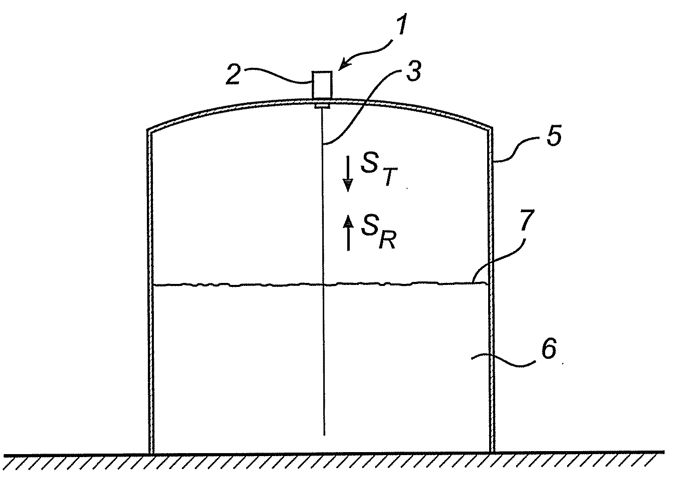
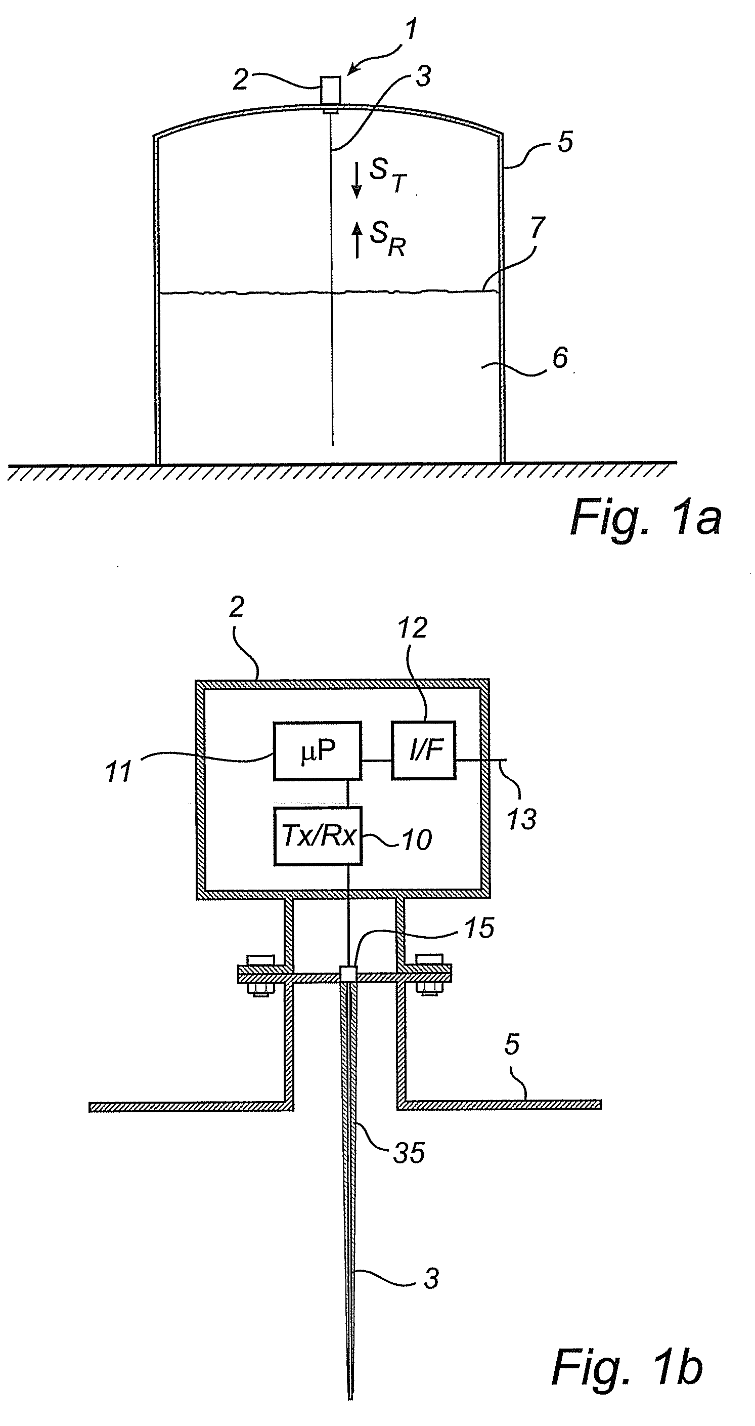
[0059]In the present detailed description, various embodiments of the radar level gauge system according to the present invention are mainly discussed with reference to a pulsed guided wave radar (GWR) level gauge system utilizing a rigid single line probe. It should be noted that this by no means limits the scope of the present invention, which is equally applicable to GWR-systems being equipped with various other kinds of probes, such as twin-line probes, coaxial probes, flexible probes, etc.

[0060]Furthermore, reference is mainly made to filling level determination through measuring the time between transmitted and reflected pulses. As is, however, evident to the person skilled in the relevant art, the teachings of the present invention are equally applicable to radar level gauge systems utilizing phase information for determining the filling level through, for example, frequency-modulated continuous wave (FMCW) measurements.

[0061]When pulses modulated on a carrier are used, phase...


PUM


Abstract

A radar level gauge system, for determining a filling level of a product contained in a tank, the radar level gauge system comprising: a transceiver for generating, transmitting and receiving electromagnetic signals; a probe electrically connected to the transceiver at a probe-transceiver connection and arranged to extend towards and into the product contained in the tank, for guiding a transmitted signal from the transceiver towards a surface of the product, and for returning a surface echo signal resulting from reflection of the transmitted signal at the surface back towards the transceiver; an impedance matching device arranged to extend along a portion of the probe inside the tank, an extension of the impedance matching device, in a direction perpendicular to the probe, decreasing along the portion of the probe with increasing distance from the probe-transceiver connection, to thereby provide impedance matching between an impedance of the probe-transceiver connection and an impedance of the probe; and processing circuitry connected to the transceiver for determining the filling level based on the surface echo signal.

Description

TECHNICAL FIELD OF THE INVENTION [0001]The present invention relates to a radar level gauge system of the GWR (Guided Wave Radar) type for determining a filling level of a product contained in a tank.TECHNICAL BACKGROUND [0002]Radar level gauge (RLG) systems are in wide use for determining the filling level of a product contained in a tank. Radar level gauging is generally performed either by means of non-contact measurement, whereby electromagnetic signals are radiated towards the product contained in the tank, or by means of contact measurement, often referred to as guided wave radar (GWR), whereby electromagnetic signals are guided towards and into the product by a probe acting as a waveguide. The probe is generally arranged to extend vertically from the top towards the bottom of the tank. The probe may also be arranged in a measurement tube, a so-called chamber, that is connected to the outer wall of the tank and is in fluid connection with the inside of the tank.[0003]The trans...

Claims


Application Information

Patent Timeline
Patent Type & Authority Applications(United States)
IPC IPC(8): G01S13/08
CPCG01F23/284G01S7/03H01Q1/225G01S13/88G01S13/08
Inventor EDVARDSSON, OLOV
Owner ROSEMOUNT TANK RADAR
Why Eureka
Try Eureka