Reverberation chamber

a reverberation chamber and chamber technology, applied in the field of electromagnetic testing, can solve the problems of significant electromagnetic excitation, affecting the excitation power of the object to be tested, and sometimes illusory robustness observed

Inactive Publication Date: 2009-12-10
EURON AERONAUTIC DEFENCE & SPACE
View PDF9 Cites 21 Cited by
  • Summary
  • Abstract
  • Description
  • Claims
  • Application Information

AI Technical Summary

Benefits of technology

[0013]In the aspects of the disclosed embodiments, the antenna in the chamber is deemed to have has a main direction of emission. To further increase the variety of cavity modes available, it is then planned to modify the main direction of radiation of the antenna in the chamber, i.e. relative to a referential system in which it is mounted. In one approach, the antenna is external to the stirrer. If necessary in this case, the antenna could be separated from the object by a screen or else it could be oriented with its major lobe in a direction opposite that of this screen so that the main direction of irradiation of the antenna preferably cannot attain the object directly. The idea is to obtain at least a certain number of reflections before the wave reaches the object. Acting in this way procures the greatest variety of excited modes while, at the same time, recourse is had to a relatively simple construction chamber (whose walls are preferably fixed).

Problems solved by technology

In practice, the robustness observed was sometimes illusory.
Indeed, the greater the chamber, the more likely it is that numerous cavity stationary modes will develop therein, leading to significant electromagnetic excitation at the position of the object.
Such an approach however has the drawback in which the excitation power to which the object to be tested is subjected depends on the volume of the chamber.
The excitation power may become prohibitive.
In the disclosed embodiments, it was observed by measurements that, ultimately, making geometrical modifications in the walls through the use of a stirrer as recommended in the above document but did not necessarily lead to a sufficiently significant increase in the extensive variety of excitation situations, barring the use of very large-sized stirrers which would considerably reduce the payload volume of the chamber.

Method used


Image

  • Reverberation chamber

Examples


Embodiment Construction

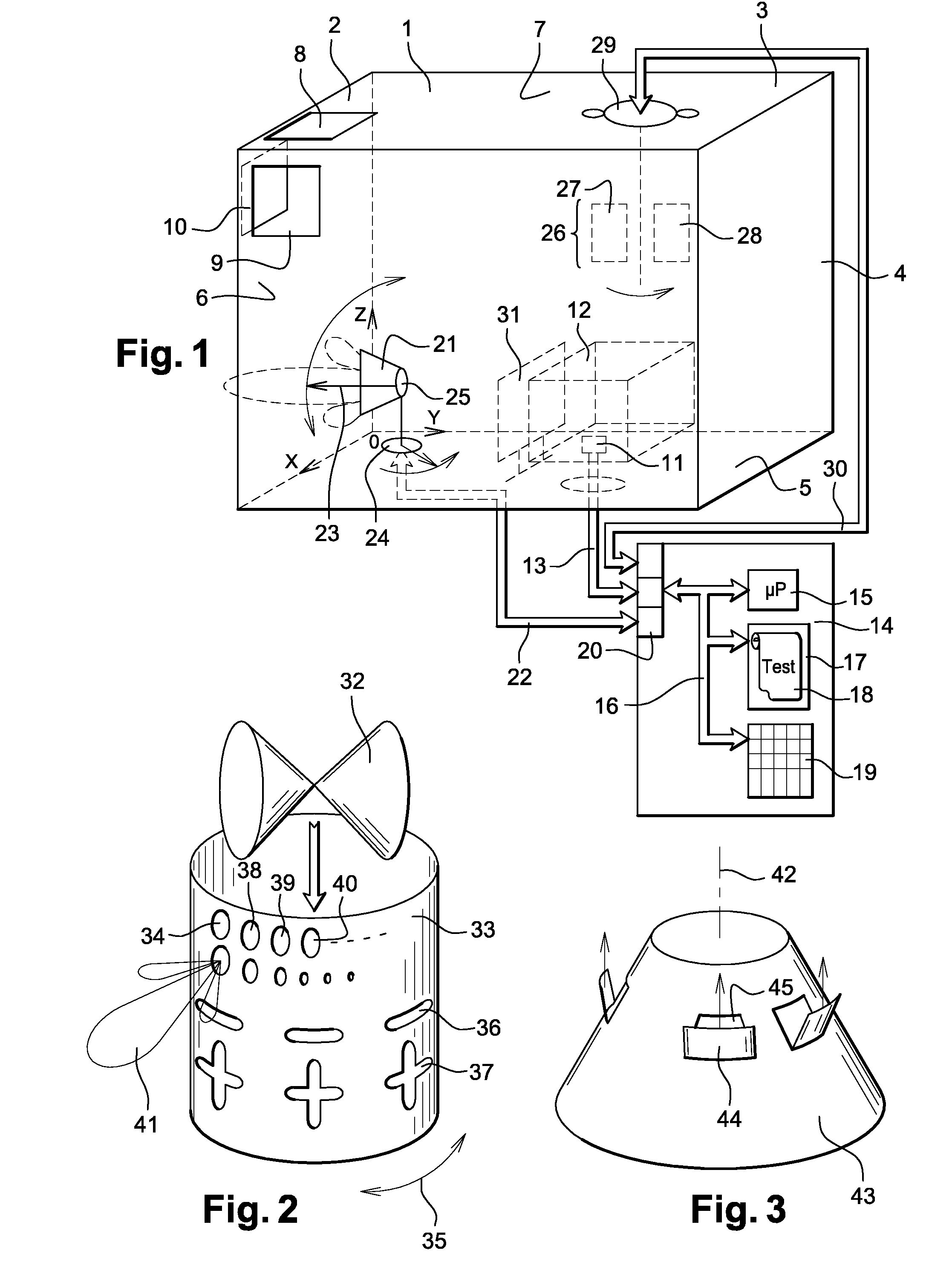
[0019]FIG. 1 shows a reverberation chamber 1 according to the aspects of the disclosed embodiments. This chamber 1 has walls such as 2 to 7 which are preferably reflective walls, for example all lined with metallization, especially metal plates such as the plates 8 to 10. The chamber 1 is preferably closed on all its faces. Since the walls 2 to 7 are designed to reflect waves, it is possible rather making a metallization to provide for a gradient of refraction indices to obtain an effect of the same order. The chamber 1 furthermore has a support 11 to support an object 12 subjected to a radiation test. The object 12 may be any unspecified object but preferably an electronic type of object. It may for example be a satellite, an instrument panel of an aircraft, a microcomputer frame or any other apparatus. The object 12 is furthermore connected by a communications and power supply bus 13 to a test management device 14. This device 14, by its principle, will have a microprocessor 15 co...


PUM


Abstract

To construct a reverberation chamber, a chamber provided with reflecting walls contains an antenna and a field stirrer which are placed opposite an object to be tested. By modifying an orientation of a main direction of irradiation from the antenna, a very large number of cavity modes are created inside the chamber, achieving the required variety of possible impingements on the object to be tested, such that the test carried out is as conclusive as possible and the least dependent possible on the dimensions and characteristics of the chamber.

Description

CROSS-REFERENCE TO RELATED APPLICATIONS[0001]This application is the National Stage of International Application No. PCT / FR2007 / 051871, International Filing Date 5 Sep. 2007, which designated the United States of America and which International Application was published under PCT Article 21 (2) as WO Publication No. WO2008 / 031964 A2 and which claims priority to French Application No. 06 53749, filed 14 Sep. 2006, the disclosures of which are incorporated herein by reference in their entireties.BACKGROUND[0002]1. Field[0003]The aspects of the disclosed embodiments are directed to an element of a reverberation chamber that can be used in electromagnetic testing.[0004]2. Brief Description of Related Developments[0005]In the field of the electromagnetic testing, especially the testing of electromagnetic compatibility and also the testing of resistance to electromagnetic stress, there are known ways of subjecting devices to electromagnetic excitation and of measuring their behavior. In c...

Claims


Application Information

Patent Timeline
Patent Type & Authority Applications(United States)
IPC IPC(8): G01R29/08H01Q3/00
CPCG01R29/0821G01R29/08G01R29/10
Inventor KOSDIKIAN, FREDERIKMAURICE, OLIVIERURREA, OLIVIER
Owner EURON AERONAUTIC DEFENCE & SPACE
Why Eureka
Try Eureka