Antenna structure and wireless communication device including the same

a wireless communication device and antenna technology, applied in the direction of radiating element structure, elongated active element feed, resonant antenna, etc., can solve the problems of not being able to provide the same surface-mount antenna, and not being able to achieve the same resonant frequency, so as to prevent the increase in loss of high-frequency current, reduce the cost of antenna components or wireless communication devices, and reduce the effect of reducing

Active Publication Date: 2009-12-10
MURATA MFG CO LTD
View PDF7 Cites 22 Cited by
  • Summary
  • Abstract
  • Description
  • Claims
  • Application Information

AI Technical Summary

Benefits of technology

[0014]That is, with the construction according to a preferred embodiment of the present invention, it is possible to change and adjust the resonant frequency of the antenna structure simply by changing and adjusting the position where the resonant-frequency adjusting element is disposed or the magnitude of capacitance or the value of inductance of the resonant-frequency adjusting element without changing factors such as the size or shape of the radiating electrode on the substrate or the length, shape, or width of the ground line. Thus, it is possible to commonly use a component (antenna component) in which a radiating electrode is disposed on a substrate for a plurality of types of wireless communication device, and this serves for

Problems solved by technology

Thus, even when the same surface-mount antenna is mounted, for example, when the type of wireless communication device varies, problematically, the resonant frequency of radio waves for wireless communications carried out by the wireless communication device (hereinafter referred to as the resonant frequency of the antenna) varies.
As described above, even when the same surface-mount antenna is provided, it is not possible to achieve the same resonant frequency of the antenna when the type of wireless communication device varies.
Thus, even when the desired resonant frequency of the antenna is the same, for example, when the type of wireless communication device varies, it is not possible to pro

Method used


Image

  • Antenna structure and wireless communication device including the same
  • Antenna structure and wireless communication device including the same
  • Antenna structure and wireless communication device including the same

Examples


Embodiment Construction

[0029]Now, preferred embodiments of the present invention will be described with reference to the drawings.

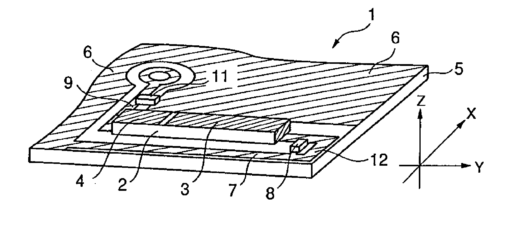
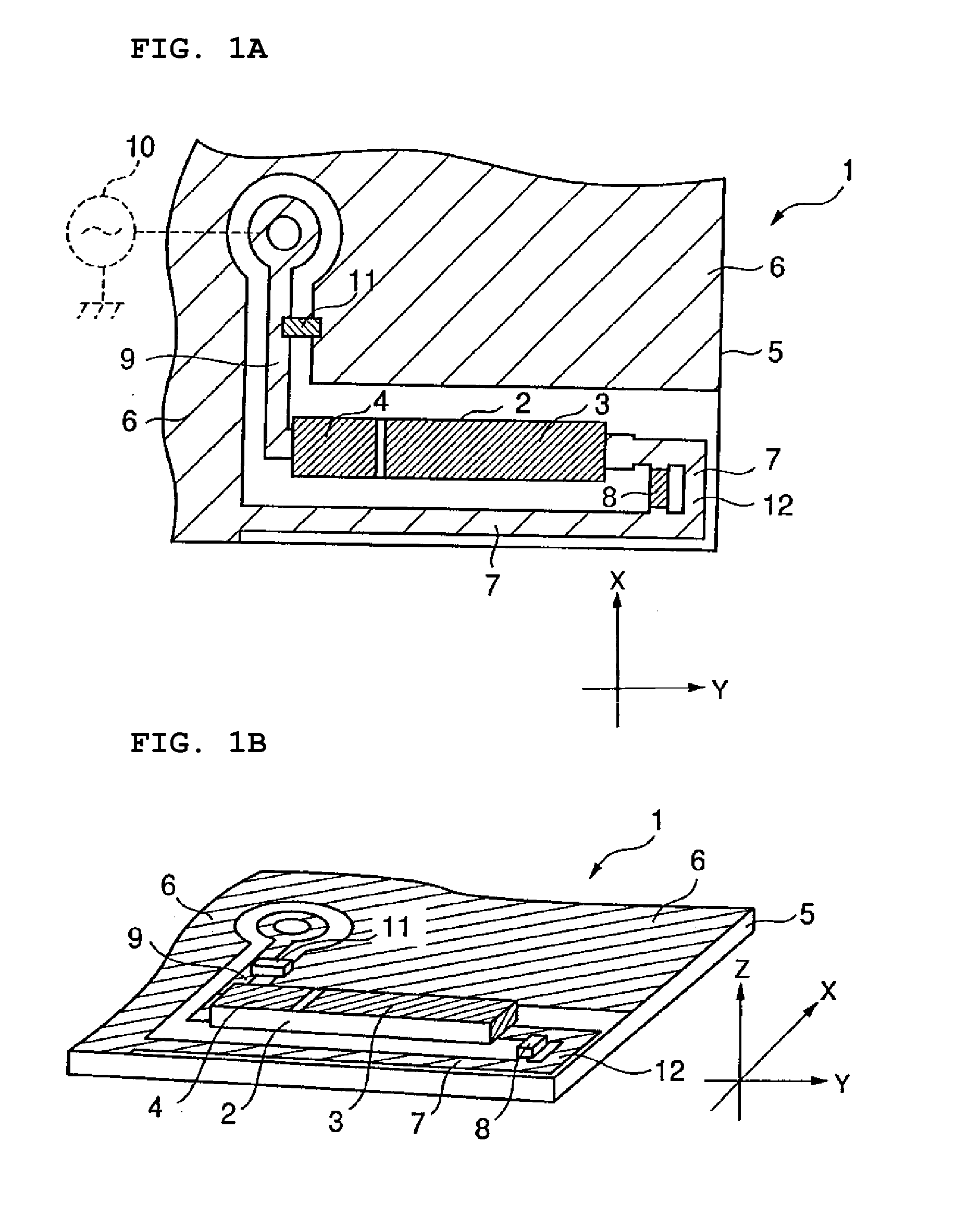
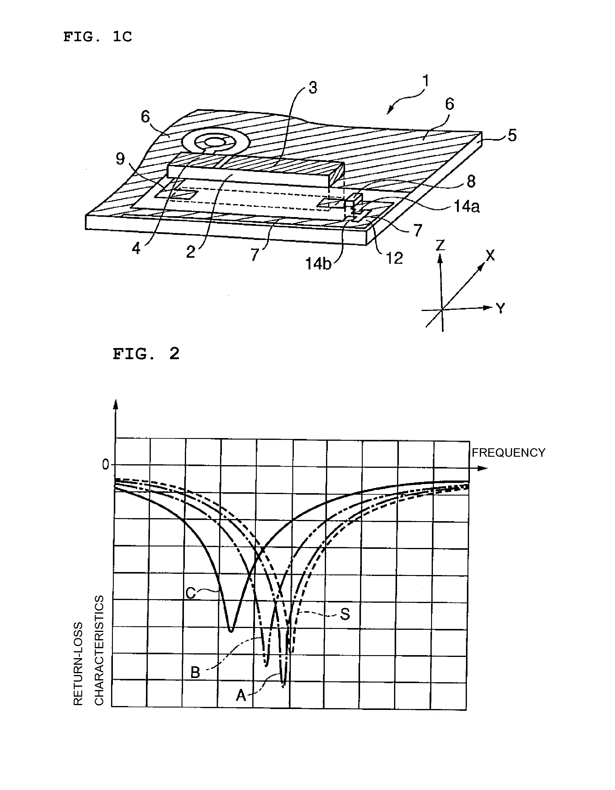
[0030]FIG. 1A is a schematic plan view showing a first preferred embodiment of an antenna structure according to the present invention. FIG. 1B is a schematic perspective view of the antenna structure shown in FIG. 1A. FIG. 1C is a schematic exploded view of the antenna structure shown in FIG. 1B.

[0031]An antenna structure 1 according to the first preferred embodiment includes a substrate 2 preferably made of a dielectric material, a radiating electrode 3 and a power-feeding electrode 4 disposed on the dielectric substrate 2, a circuit board 5 on which the dielectric substrate 2 is surface-mounted, a ground electrode 6 disposed on the circuit board 5, a ground line 7 arranged on the circuit board 5 so that the radiating electrode 3 of the dielectric substrate 2 is electrically connected to the ground electrode 6 of the circuit board 5, a resonant-frequency adjusting element 8 d...


PUM


Abstract

A capacitive-power-feeding-type radiating electrode is provided on a dielectric substrate, and the dielectric substrate is provided in a non-ground region of a circuit board. In the non-ground region of the circuit board, a ground line electrically connecting the radiating electrode with a ground electrode of the circuit board is provided. The ground line is shaped so as to have at least one turnback portion. On the ground line, a resonant-frequency adjusting element is arranged so as to shortcut a portion of the ground line. The resonant-frequency adjusting element has a capacitance or inductance so as to adjust a resonant frequency of an antenna structure to a predetermined resonant frequency.

Description

BACKGROUND OF THE INVENTION[0001]1. Field of the Invention[0002]The present invention relates to an antenna structure including a capacitive-power-feeding-type radiating electrode and to a wireless communication device including the antenna structure.[0003]2. Description of the Related Art[0004]As a type of antenna provided on a wireless communication device, a surface-mount antenna that is mounted on a circuit board of a wireless communication device and contained and disposed within a case of the wireless communication device exists. In the surface-mount antenna, for example, a radiating electrode that performs an antenna operation is formed on a dielectric substrate.[0005]The frequency characteristics of radio waves of a wireless communication device in which a surface-mount antenna is mounted on a circuit board are not determined only by a radiating electrode of the surface-mount antenna, but are determined by various factors such as a ground electrode or portions of the circuit...

Claims


Application Information

Patent Timeline
IPC IPC(8): H01Q9/00H01Q1/38
CPCH01Q1/243H01Q1/38H01Q9/42H01Q9/30H01Q9/40H01Q9/0421
Inventor HIRANO, SATORU
Owner MURATA MFG CO LTD
Why Eureka
Try Eureka