Switching power source system

a power source system and switching technology, applied in the direction of electric variable regulation, process and machine control, instruments, etc., can solve the problems of achieve the effects of reducing noise, enhancing power factor, and reducing high frequency noise and switching loss

Active Publication Date: 2009-12-10
FUJI ELECTRIC CO LTD
View PDF4 Cites 28 Cited by
  • Summary
  • Abstract
  • Description
  • Claims
  • Application Information

AI Technical Summary

Benefits of technology

[0019]According to the invention, the turning on and the turning off of the switching device are to be carried out so that a value of a current flowing in the inductor falls between a first threshold value, in phase with and similar to the waveform of the input voltage and having an amplitude proportional to that of the error voltage signal, and a second threshold value proportional to the first threshold value. Thus, the turning on and turning off of the switching device are carried out automatically with optimum durations depending on conditions of an input voltage and conditions of a load without the on duration or the off duration being fixed. This makes it possible to enhance the power factor. In addition, a switching frequency is varied by changing the on duration and off duration to disperse the spectrum of generated noise to provide noise reduction. Furthermore, limiting the switching frequency by limiting the on duration and off duration reduces high frequency noise and switching loss.

Problems solved by technology

Furthermore, limiting the switching frequency by limiting the on duration and off duration reduces high frequency noise and switching loss.

Method used


Image

  • Switching power source system
  • Switching power source system
  • Switching power source system

Examples


Embodiment Construction

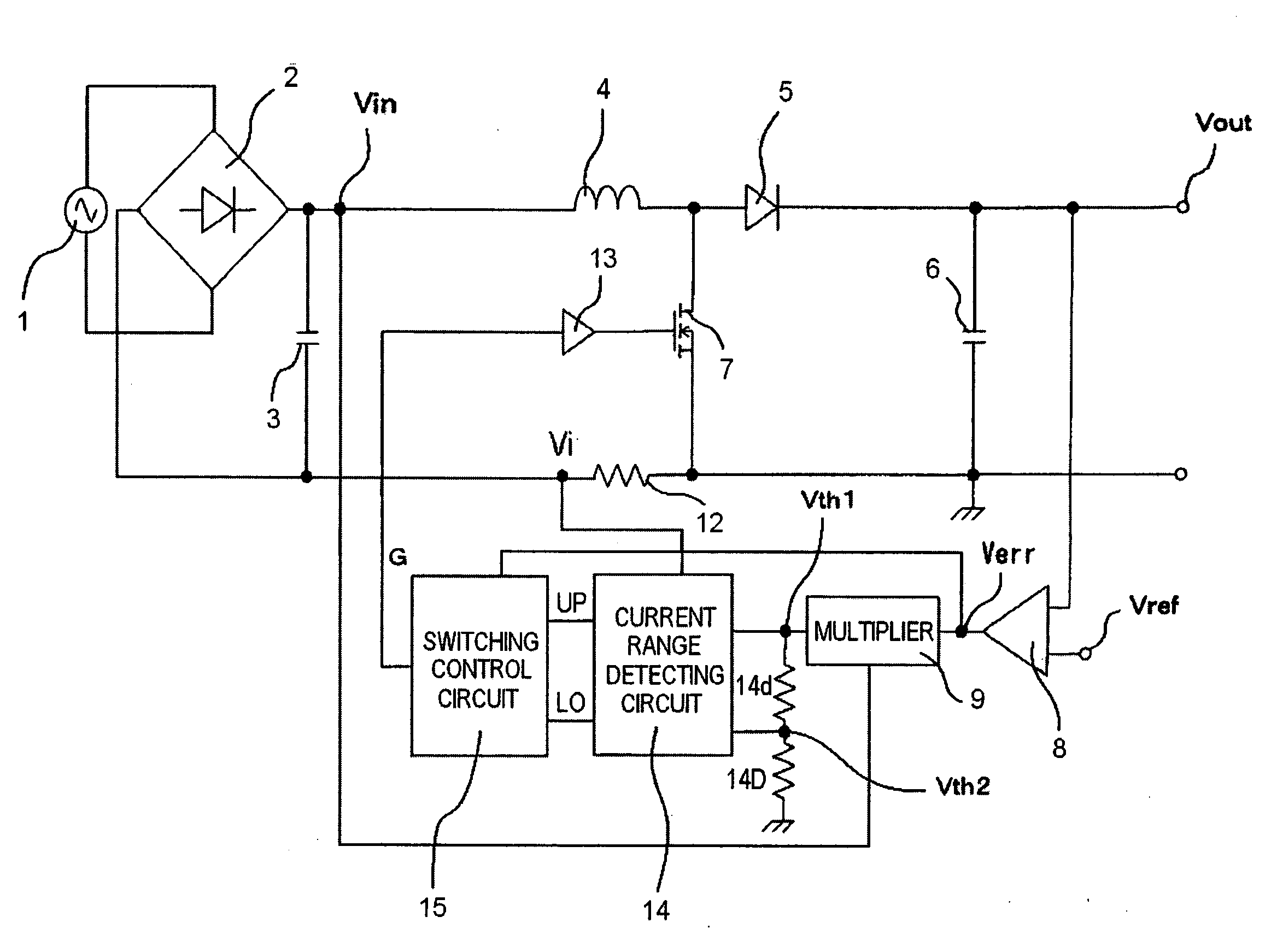
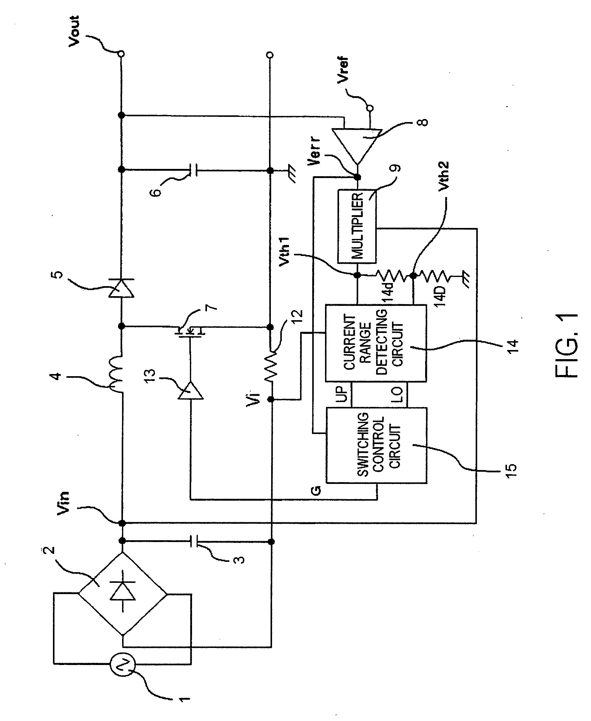
[0033]FIG. 1 is a circuit diagram showing the circuit configuration of a switching power source system according to an embodiment of the invention. In FIG. 1, the same constituents as those in the example of the related switching power source system shown in FIG. 6 will be denoted with the same reference numerals and signs with explanations thereof omitted.

[0034]An AC voltage outputted from an AC power source 1 is subjected to full-wave rectification in a rectifier circuit 2 formed of a diode bridge to be a Rectified voltage, from which high frequency noise is removed by a capacitor 3. The rectified voltage is supplied to a capacitor 6 through an inductor 4 and a diode 5 and is thereby smoothed. The smoothed rectified voltage is outputted as a DC output voltage Vout. A switching device 7, such as a MOSFET, is connected across a point between the inductor 4 and the diode 5 and a point at ground potential to turn a current flowing from the inductor 4 to the diode 5 on and off.

[0035]A ...


PUM


Abstract

An error voltage Verr, being a difference between DC output voltage Vout and output reference voltage Vref, and an input voltage Vin are multiplied to produce first threshold voltage signal Vth1 in phase with and similar to input voltage Vin and proportional to Verr. Second threshold voltage signal Vth2 is produced from first threshold voltage signal Vth1. The input current is detected as a current detection signal Vi across a resistor 12, whether it is between the threshold value signals is detected by a current range detecting circuit, and accordingly, the timing of turning on or off switching device is controlled so that at least one of an duration on and an off duration of the switching device is limited to enhance a power factor. Unfixed off duration disperses a noise spectrum to prevent an increase in switching frequency, to reduce noise.

Description

CROSS-REFERENCE TO RELATED APPLICATION[0001]This application claims the foreign priority benefit under 35 USC §119 of Japanese application ser. No. JP PA 2008-150166, filed Jun. 9, 2008, the entire disclosure of which is incorporated herein by reference.BACKGROUND OF THE INVENTION[0002]1. Field of the Invention[0003]The present invention relates to a switching power source system with a power factor correcting mode in which a stable DC power source is formed from an AC power source and is operated so that an input voltage and an input current to a chopper circuit are approximately in phase and have similar waveforms.[0004]2. Background Art[0005]Control methods of this kind for switching power source systems include a critical conduction mode control method that carries out control so as to make a switching device turned on when a coil current becomes zero and a continuous conduction mode control method that carries out control so as not to make the coil current become zero. In gener...

Claims


Application Information

Patent Timeline
Patent Type & Authority Applications(United States)
IPC IPC(8): H02M7/04
CPCH02M1/4225Y02B70/126H02M1/44Y02B70/10
Inventor SHIMIZU, HIDEOAMANO, ISAO
Owner FUJI ELECTRIC CO LTD
Why Eureka
Try Eureka