Ct scanner with scatter radiation correction and method of using same

a scatter radiation and scanner technology, applied in the field of computed tomography (ct) imaging, can solve the problems of cross scattering increasing the scattering problem, local contrast and data accuracy deterioration, and the accuracy of this correction method is rather limited

Active Publication Date: 2009-12-10
ARINETA
View PDF1 Cites 29 Cited by
  • Summary
  • Abstract
  • Description
  • Claims
  • Application Information

AI Technical Summary

Benefits of technology

[0041]Unless otherwise defined, all technical and scientific terms used herein have the same meaning as commonly understood by one of ordinary skill in the art to which this invention belongs. Although methods and materials similar or equivalent to those described herein can be used i...

Problems solved by technology

Due to scattered X-ray photons, the local contrast and the data accuracy are deteriorated.
Further, some CT scanners use multiple sources of X rays associated with multiple detectors and the cross scattering increases the scattering problem.
The accuracy of this correction method is rather limited due to the high variability of scanned subjects.
However, none of these methods provid...

Method used


Image

  • Ct scanner with scatter radiation correction and method of using same
  • Ct scanner with scatter radiation correction and method of using same
  • Ct scanner with scatter radiation correction and method of using same

Examples


Embodiment Construction

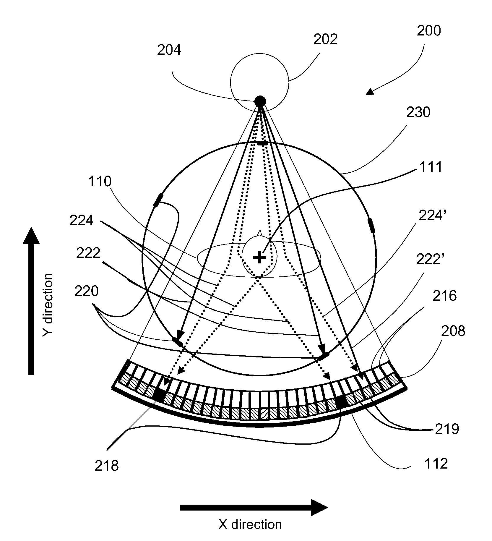
[0056]The present invention relates to Computed Tomography (CT) imaging. More specifically, it relates to measurement and compensation of scattered radiation in wide beam CT scanners

[0057]Before explaining at least one embodiment of the invention in detail, it is to be understood that the invention is not limited in its application to the details of construction and the arrangement of the components set forth in the following description or illustrated in the drawings. The invention is capable of other embodiments or of being practiced or carried out in various ways. Also, it is to be understood that the phraseology and terminology employed herein is for the purpose of description and should not be regarded as limiting.

[0058]In discussion of the various figures described herein below, like numbers refer to like parts.

[0059]The drawings are generally not to scale. For clarity, non-essential elements were omitted from some of the drawings.

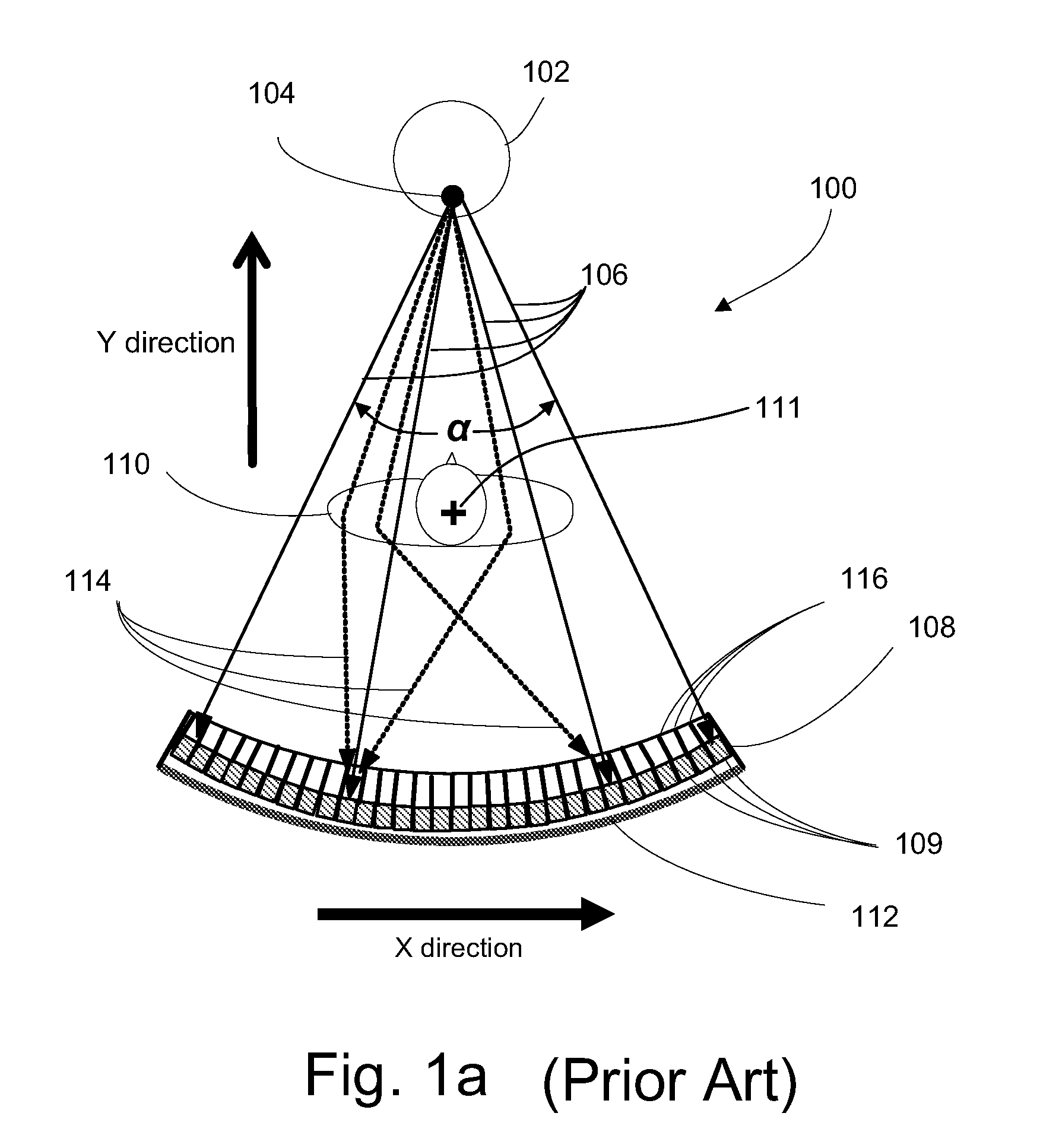
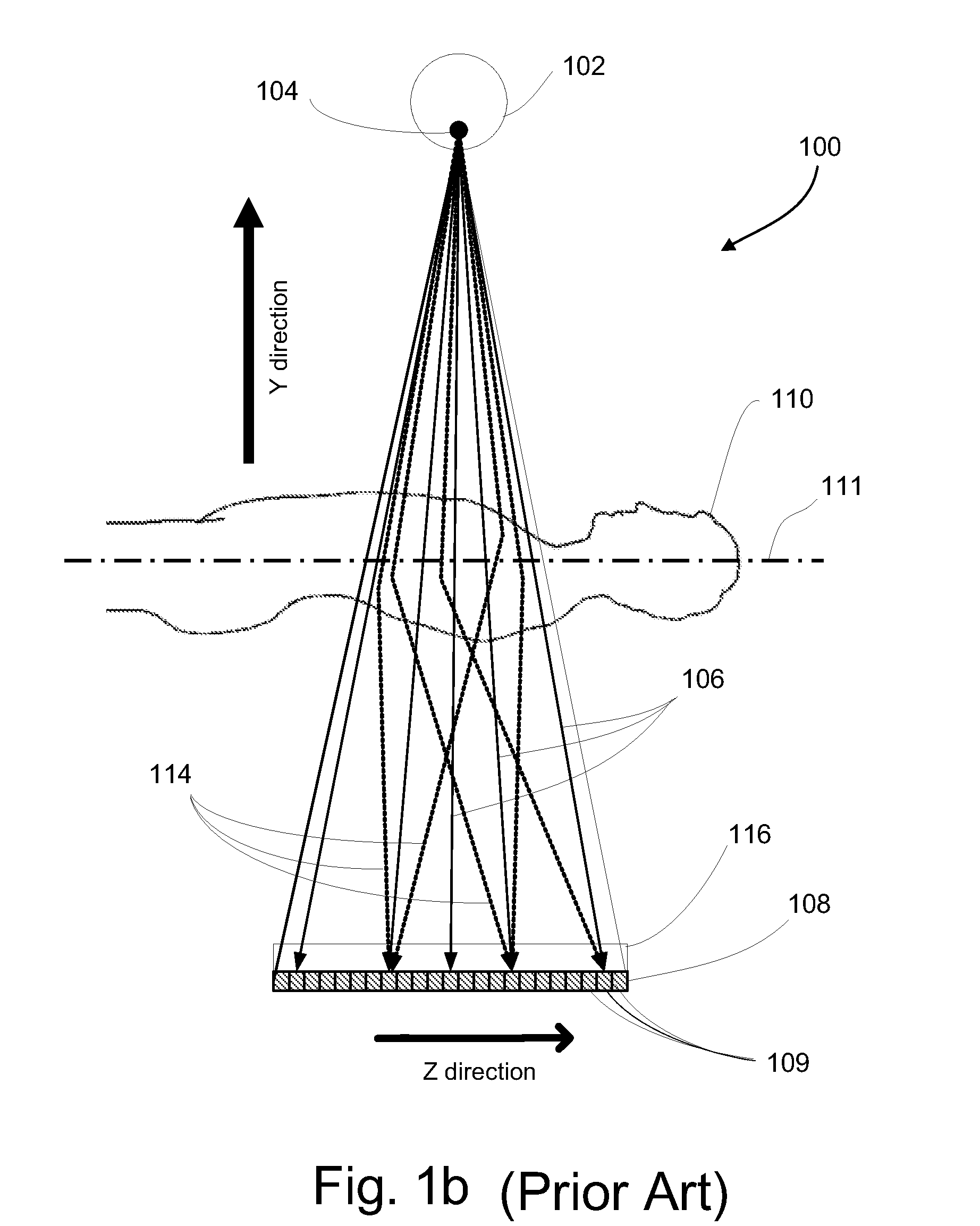
[0060]FIG. 1a schematically depicts a front vi...


PUM


Abstract

A CT scanner with scatter correction device and a method for scatter correction are provided. The method of correcting CT images from artifacts caused by scattered radiation comprises affixing to the non-rotating frame of the CT gantry a plurality of shields for shielding some of the CT detector elements from direct X ray radiation, while allowing scattered radiation to arrive at said shielded elements; measuring scatter signals from said shielded elements, indicative of scattered radiation intensity; and correcting for scatter by subtracting scatter intensity values estimated from said measured scatter signals from signals measured by unshielded detector elements.

Description

CROSS-REFERENCE TO RELATED APPLICATION[0001]This application is based upon and claims the benefit of U.S. Provisional Application Ser. No. 61 / 131,302, filed Jun. 09, 2008 and entitled “CT scanner with scatter radiation correction and method of using the same”, the entire contents of which are incorporated by reference as if fully set forth herein.FIELD OF THE INVENTION[0002]The present invention relates to Computed Tomography (CT) imaging. More specifically, it relates to measurement and compensation of scattered radiation in wide beam CT scanners.BACKGROUND OF THE INVENTION[0003]Computed Tomography (CT) is a common imaging technique based on measurements of X-ray attenuation in the scanned subject in multiplicity of projection angles. X-rays are attenuated by either absorption or scattering, in which case they may still reach the detector and be detected. Scatter radiation reduction and correction are required for both medical and nonmedical X ray CT imaging applications. Due to sc...

Claims


Application Information

Patent Timeline
IPC IPC(8): H05G1/60
CPCA61B6/032A61B6/4014A61B6/4085A61B6/4266A61B6/4028A61B6/5282G01T1/2985H04N5/32A61B6/4291
Inventor RUIMI, DAVIDSHAPIRO, OLGADAFNI, EHUD
Owner ARINETA
Why Eureka
Try Eureka