Method and apparatus for directed device placement in the cerebral ventricles or other intracranial targets

a technology of directed device placement and target, which is applied in the field of intracranial access, can solve the problems of harm to patients, inability to accurately place devices in the intracranial cavity, and difficulty in accurate placement, and achieve the effects of small modification, easy learning curve, and easy adaptation

Active Publication Date: 2009-12-10
FLINT ALEXANDER C
View PDF19 Cites 15 Cited by
  • Summary
  • Abstract
  • Description
  • Claims
  • Application Information

AI Technical Summary

Benefits of technology

[0025]The method of the invention employs many tools familiar to practitioners (standard drill and bit, catheter or othe

Problems solved by technology

Accurate intracranial placement of devices is challenging.
Stated another way, the conventional approach, representing a current standard of practice, is essentially “blind”, entailing some degree of guesswork, and as a result the placement is not always satisfactorily accurate.
Misplaced devices may be ineffective, and may result in harm to the patient.
Repeated placement efforts increase risks of injury or trauma to the patient, such as bleeding or damage to brain tissue or infection.
Ultrasound probes typically produce a beam that is the same size a

Method used


Image

  • Method and apparatus for directed device placement in the cerebral ventricles or other intracranial targets
  • Method and apparatus for directed device placement in the cerebral ventricles or other intracranial targets
  • Method and apparatus for directed device placement in the cerebral ventricles or other intracranial targets

Examples


Embodiment Construction

[0048]The invention will now be described in further detail by reference to the drawings, which illustrate alternative embodiments of the invention. The drawings are diagrammatic, showing features of the invention and their relation to other features and structures, and are not made to scale. For improved clarity of presentation, in the FIGs. illustrating embodiments of the invention, features corresponding to features shown in other drawings are not all particularly renumbered, although they are all readily identifiable in all the FIGs.

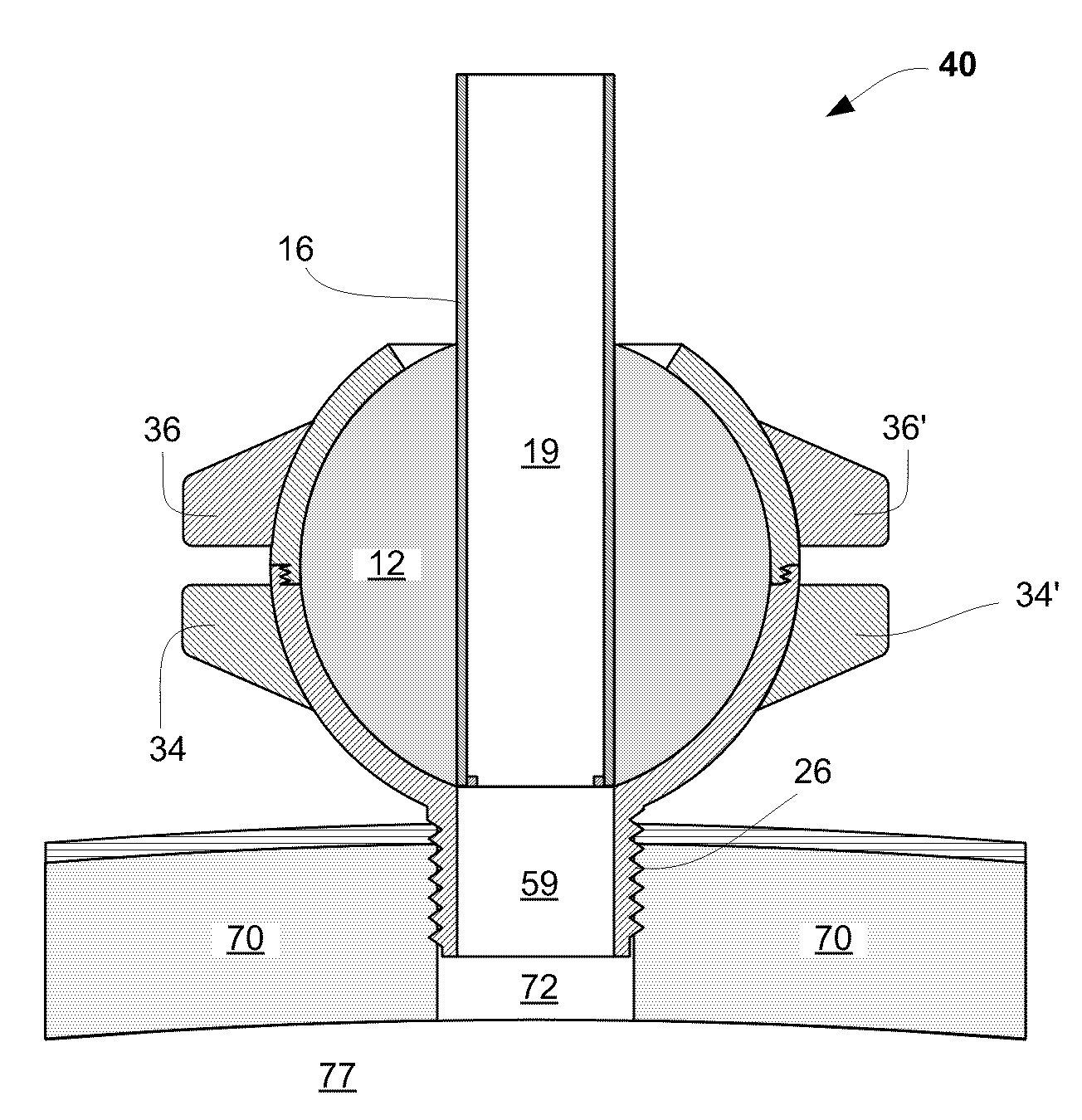
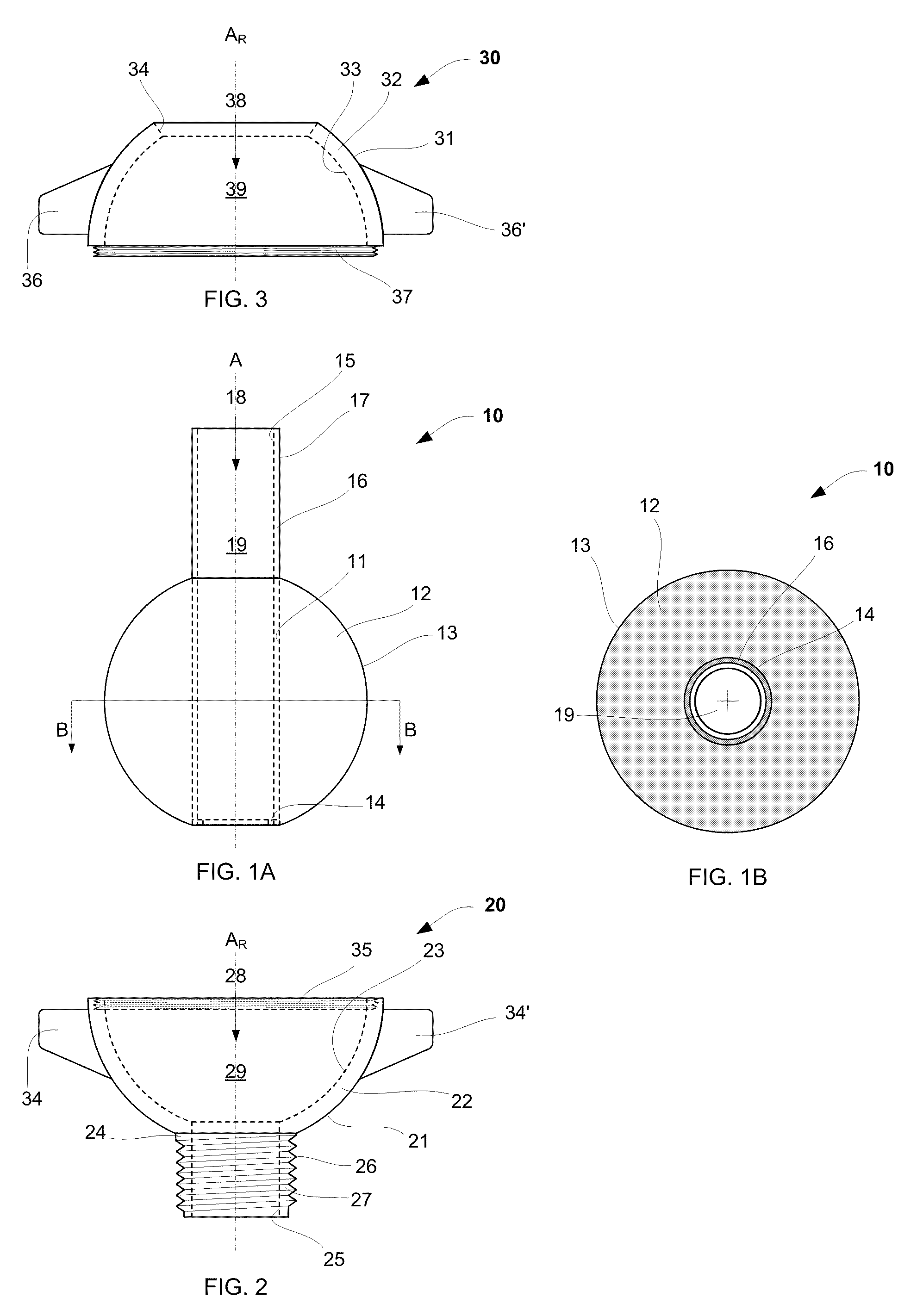
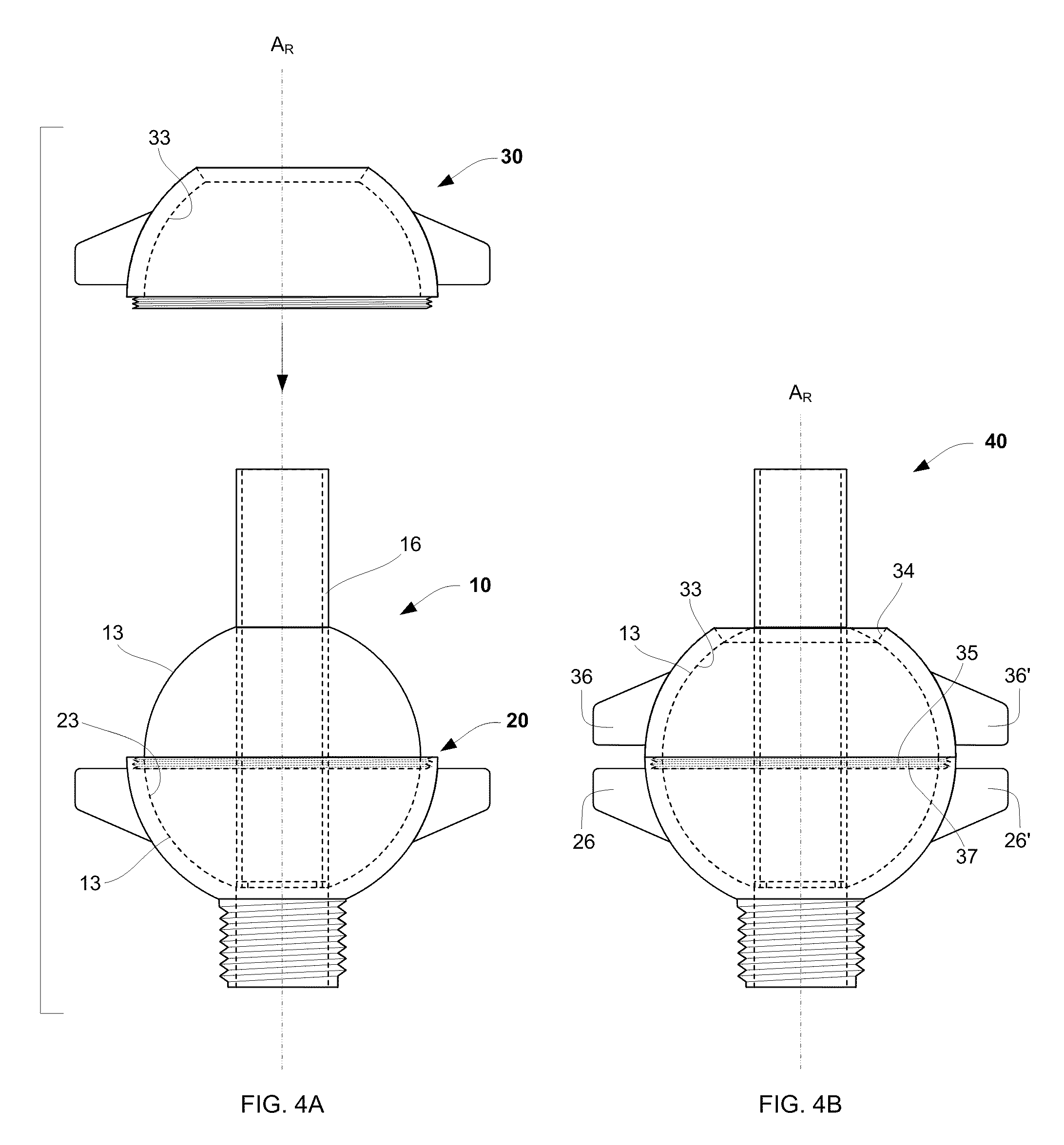
[0049]In various embodiments, cranial access apparatus includes a guidepiece mounted in a receptacle. The receptacle includes a lower part (cup) and an upper part (cover). The guidepiece includes a body having the form of a ball having a bore through the center, and a guide tube in the bore. In some embodiments the guide tube projects from the body, constituting a receiving end of the guidepiece. The parts of the receptacle are configured so that whe...


PUM


Abstract

Apparatus for directed cranial access to a site includes a guidepiece and a receptacle. The receptacle includes a lower part having a rim and a base, and a hollow stem at the base adapted to be mounted in a hole in the skull; and an upper part having a rim and an opening at the top. Each part of the receptacle has an interior spherical surface, and they can be joined at the rims to form an inner surface enclosing a spherical interior. The guidepiece includes a body having a spherical outer surface and a cylindrical bore through the center, defining an alignment axis; and a guide tube in the bore. The guidepiece is dimensioned to fit rotatably within the receptacle interior, and the apparatus is assembled by joining the receptacle over the guidepiece body, with the guide tube projecting through the top opening. The guide tube is dimensioned to accept an imaging device such as an ultrasound probe during an imaging stage, and an adaptor is provided, dimensioned to accept a device to be placed at the site during a placement stage. The probe is inserted into the guide tube and the guidepiece is swiveled until the image shows that the alignment axis is aligned along an optimal trajectory to the site, the receptacle is tightened to lock the guidepiece, and the imaging device is withdrawn. Then the adaptor is inserted into the guide tube, and the device is inserted through the adaptor along the established trajectory to the site. After placement of the device into the intracranial target, the adaptor, guidepiece, and receptacle are removed as a unit over the device while the device is held in place.

Description

CROSS-REFERENCE TO RELATED APPLICATIONS[0001]This application claims priority from U.S. Provisional Application No. 61 / 059,371, by Alexander Calhoun Flint, titled “Catheterization of the cerebral ventricles by an ultrasound-aligned guidance system”, which was filed Jun. 6, 2008, and which is hereby incorporated by reference.BACKGROUND[0002]1. Field of the Invention[0003]This invention relates to intracranial access. Generally, this invention relates to using imagery to establish a trajectory and distance for introduction of a device to a site in the brain and, more particularly, to directed placement of a device to the cerebral ventricles.[0004]2. Description of Related Art[0005]Features in and around the brain (the intracranial contents) may be accessed for diagnosis or treatment by way of a hole drilled through the skull. Accessing the intracranial contents may include introducing a device, such as a catheter or needle, through the hole to a particular site.[0006]It may be necessa...

Claims


Application Information

Patent Timeline
IPC IPC(8): A61B17/34A61B8/00
CPCA61B8/00A61B8/4209A61B8/0808A61B2019/208A61B2019/5276A61B19/201A61B2090/103A61B90/11A61B2090/378A61B8/12A61B17/3423A61M27/006A61M2205/04A61M2210/0693
Inventor FLINT, ALEXANDER C.
Owner FLINT ALEXANDER C
Why Eureka
Try Eureka