
Therapeutic method and device for rehabilitation

a therapy method and a technology for rehabilitation, applied in the field of functional rehabilitation, can solve the problems of not providing joint support or muscle support or augmentation, little if any direct benefit to mobility, and generally not providing rehabilitation or the development of unassisted mobility

Inactive Publication Date: 2009-12-10
TIBION
View PDF100 Cites 67 Cited by
  • Summary
  • Abstract
  • Description
  • Claims
  • Application Information

AI Technical Summary

Benefits of technology

[0008]The invention relates to a method and a system for increasing the functional capability of joints, particularly in a rehabilitative sense, where the volitional range of motion of a patient may be improved, and where the effective control over joint movement within that range is increased. Rehabilitation of the functional capability of joints occurs through a number of physiological processes, including building of strength and retraining of neural pathways. Basically, the method includes fastening a powered device at sites above and below a joint of a subject so the device is able to control movement of the joint, the patient moving the joint volitionally within a range of motion substantially without assistance of the device, and then, moving the joint beyond that volitional range of motion substantially with the support of the device.
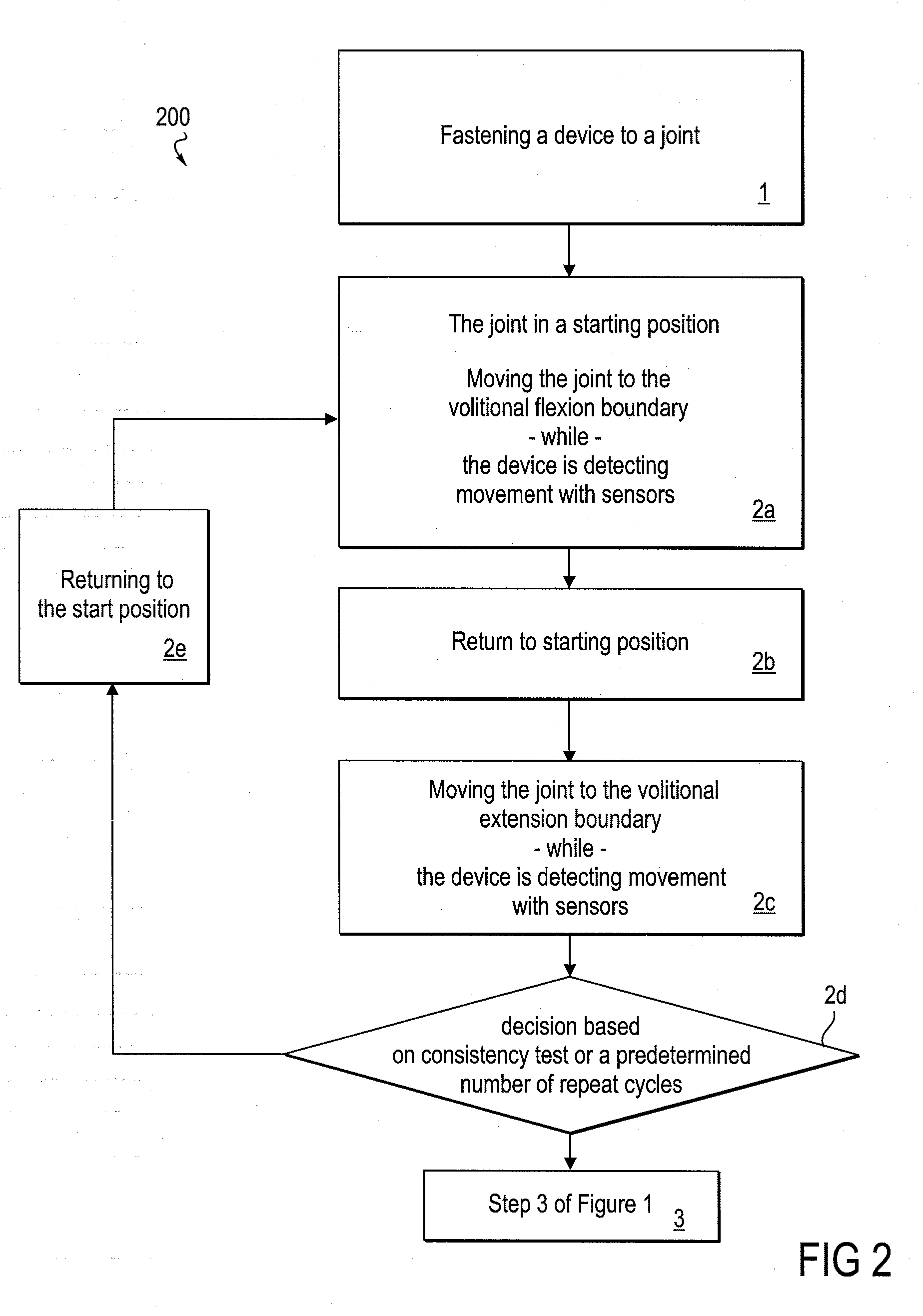
[0012]In some embodiments of the method, moving a joint to the volitional boundary is repeated one or more times prior to moving the joint to the expanded boundary of the rehabilitative range. As will be seen below, the movement within the subject's volitional range is sensed by the device, and repetition of this movement helps to better establish the volitional range boundary.
[0013]In some embodiments of the method, moving to the volitional boundary occurs substantially without assistance from the powered device, and is thus substantially under the control of the subject. In some particular embodiments of the method, moving to the volitional boundary may occur with a level of assistance from the powered device that counteracts at least a portion of gravitational force. In some embodiments of the method, the assistance in moving provided by the powered device includes the device permitting movement only in the direction of the expanded boundary in a ratchet-like manner, thus allowing the patient an opportunity to move the joint from an angle that is beyond the range where the joint would be volitionally.
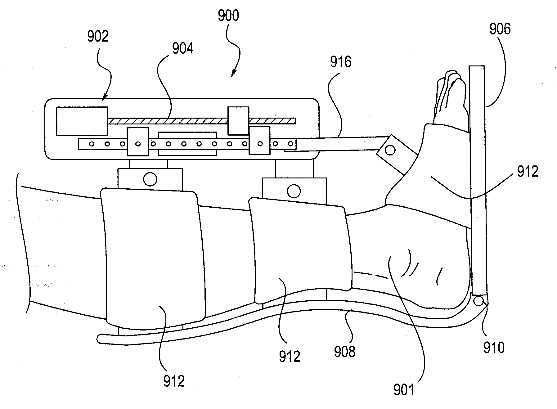
[0029]In various embodiments of the system, the controller is configured to activate the actuator to move the joint beyond the volitional boundary and then to the boundary of an expanded range of motion. In some embodiments, the controller is configured to have the actuator counteract at least in part the effect of gravity on movement of the joint even when the joint is substantially under the volitional control of the subject. And in some embodiments of the system, an actuator force sensor is operably connected to the controller and providing input thereto, the controller capable of limiting the maximal force applied to the actuator.

Problems solved by technology

Strength training devices, their strength building benefits notwithstanding, provide little if any direct benefit toward mobility, nor do they provide joint support or muscle support or augmentation.
Passive assistance devices, such as canes, crutches, walkers and manual wheelchairs, can very effectively assist with mobility in an immediate sense, but they generally do not provide for rehabilitation or the development of unassisted mobility.
As with strength training, the devices tend to rely on functioning muscle and existing neural pathways, without a particular benefit in terms of regaining lost independent or volitional function.
Active or powered mobility devices, such as motorized wheelchairs, provide very valuable mobility benefits, but do little if anything in terms of encouraging the development of strength, or regaining independent functional mobility.
These devices, as a whole, however, do not provide rehabilitation toward device-free independent mobility.

Method used


Image

  • Therapeutic method and device for rehabilitation
  • Therapeutic method and device for rehabilitation
  • Therapeutic method and device for rehabilitation

Examples


embodiment 100

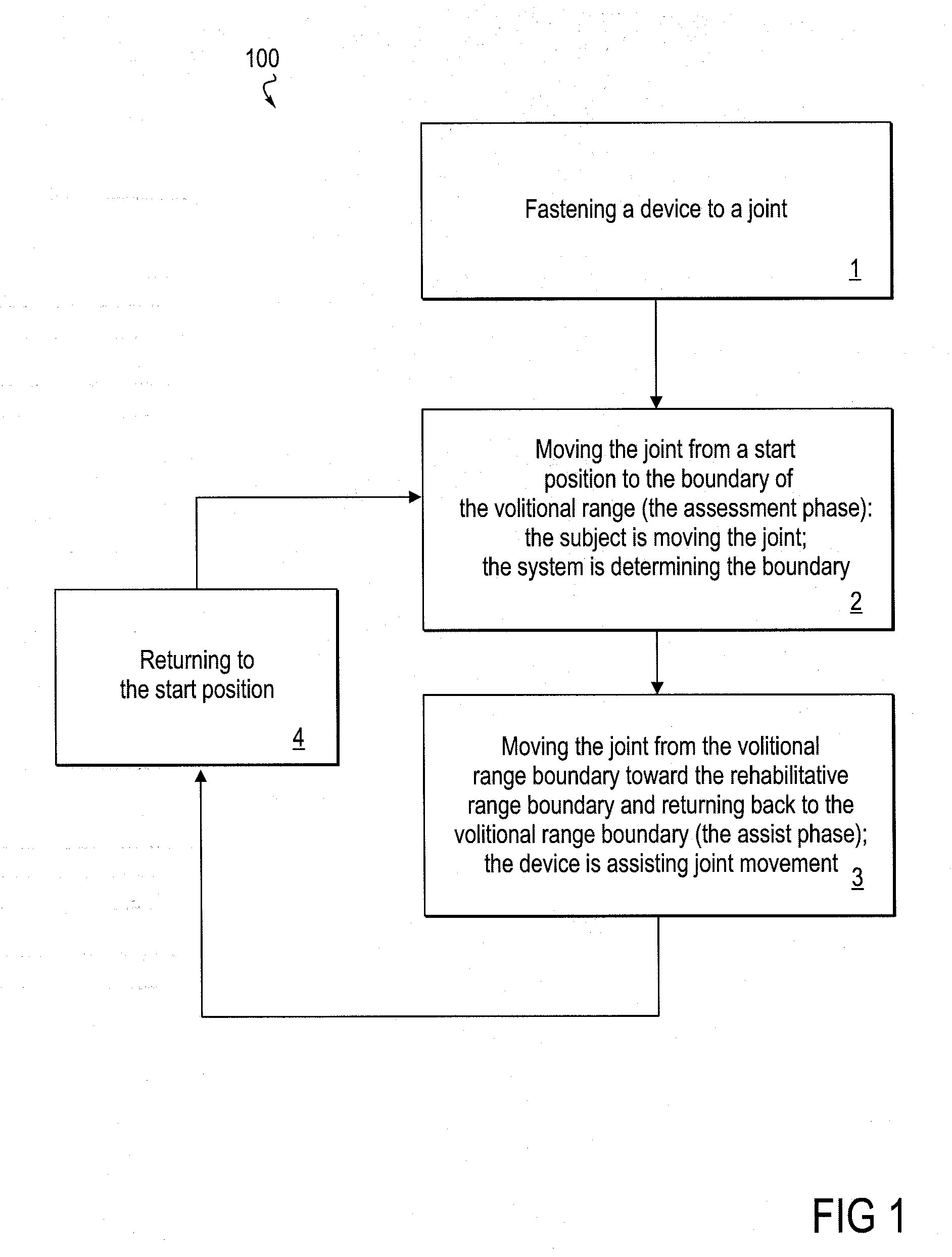
[0047]Various embodiments of the rehabilitative method of the invention are shown in the flow diagram of FIGS. 1-5. FIG. 1 depicts an embodiment 100 of the method in its most basic form. In Step 1, a powered device, or more specifically, an orthotic portion of a powered device, is fastened or applied to sites on either side of a patient's joint. In some embodiments, the method may be applied to more than one joint, in which case, fastening refers to applying an orthotic portion of a powered device at each of the respective joints. Described in the system description section below, for example, are orthotic devices that may be applied to the ankle alone, knee alone, or the combination of the ankle and knee. At the outset of a Step 2, the patient's joint is in a starting position, and the powered device is in a free movement mode that provides substantially no assistance or resistance to movement of the joint. During the Step 2, the patient volitionally moves the joint to the boundary...

embodiment 300

[0053]FIG. 3 depicts Step 3 of an embodiment 300 of the method as depicted in FIG. 1 in more detail. After completion of Steps 1 and 2, in Step 3a, the patient moves the joint to the volitional boundary. In Step 3b, the powered device assists in the movement of the joint from the boundary of volitional movement to the boundary of the extended range of motion or rehabilitative movement. This extended range of motion boundary is a controlled and predetermined boundary that may be set by various formulas or algorithms, or, for example, by the judgment of a medical professional, overseeing the therapy, or by a patient that is sufficiently informed and trained in the method. Step 3c is initiated after the limb has attained the extended range boundary, and the joint is returned with assistance back to the volitional boundary and then volitionally back to the starting point. Some embodiments may provide the return back to the starting position from the volitional boundary as an assisted mo...

embodiment 500

[0057]FIG. 5 shows another embodiment 500 of the method that expands upon the “waiting” feature of the method embodiment shown in FIG. 4, as described above. In this embodiment of the method, the volitional range of motion is continuously re-evaluated during iterations or cycles of the assist phase (Step 3 of FIG. 1) of joint movement, and the volitional range or boundary may be modified during this assist phase, rather than requiring a return to the assessment of volitional range per Step 2 of the method. This embodiment of Step 3 includes an ongoing testing, heuristic, or trial-and-error-based tuning aspect of the method that is based on the performance of the subject with regard to volitional joint movement. This testing may occur within the method in addition to the initial assessment phase that underlies the establishment of a baseline volitional boundary, i.e., the assessment phase (Step 2) as seen in FIG. 1.

[0058]As provided by this embodiment (FIG. 5), the assist phase (Step...


PUM


Abstract

The invention relates to embodiments of methods for extending a subject-controllable range of joint motion, and for increasing subject control of joint movement within a range of motion. Embodiments include fastening a powered device around a joint so as to be able to control the joint, allowing the subject to move the joint within a range of volitional motion, and then engaging the powered device to support movement of the joint into an expanded, rehabilitative range. In some embodiments, the device supports joint movement by substantially providing the force to move the joint beyond the volitional boundary. In other embodiments, supporting movement includes the subject substantially providing the force, and the device allowing movement only in a desired direction. The invention further relates to a system for increasing the functional capability of a joint by implementing embodiments of the method. By such methods and system, rehabilitation is accomplished both by building strength, and training neural pathways.

Description

INCORPORATION BY REFERENCE[0001]All publications, patents and patent applications mentioned in this specification are herein incorporated by reference to the same extent as if each individual publication, patent or patent application was specifically and individually indicated to be incorporated by reference. The application, for example, incorporates in entirety by this reference U.S. Pat. No. 7,239,065 filed Nov. 6, 2003, of Robert Horst entitled “Muscle Assistance Device and Method” and U.S. patent application Ser. No. 11 / 932,799, of Robert Horst, et al., entitled “Methods and Devices for Deep Vein Thrombosis Prevention”, filed on Oct. 31, 2007.FIELD OF THE INVENTION[0002]The invention relates to the field of the functional rehabilitation of patients who have suffered loss of function due to injury, condition, or disease. For example, the method may be therapeutically applied by patients who have experienced a stroke.BACKGROUND OF THE INVENTION[0003]There is a need for devices th...

Claims


Application Information

Patent Timeline
IPC IPC(8): A61B5/103A61B19/00A61H1/02
CPCA61H1/024A61H1/0266A61H2201/165A61H2201/5015A61H2201/5038A61H1/008A61H2201/5064A61H2201/5069A61H2230/65A63B21/00181A63B2021/0054A61H2201/5061A63B21/0054
Inventor BHUGRA, KERN S.HORST, ROBERT W.JARDINE, ROBERT L.
Owner TIBION
Learn More