
Moxibustion device

a technology of moxibustion device and heat dissipation device, which is applied in radiation therapy, therapy, therapeutic cooling, etc., can solve the problems of insufficient fixation between the far infrared radiation layer formed by coating or baking and the glass cover surface, deterioration of appearance, and deterioration of appearance, so as to reduce the heat conductivity of the heater and reduce the temperature of the heater. , the effect of rapid cooling

Inactive Publication Date: 2009-12-10
SUPER ONNETABU
View PDF2 Cites 43 Cited by
  • Summary
  • Abstract
  • Description
  • Claims
  • Application Information

AI Technical Summary

Benefits of technology

[0009]This invention is proposed in view of the above problems, and an object thereof is to provide a flat iron-like moxibustion device capable of substantially uniform far infrared ray radiation and having an excellent appearance.
[0024]Also, since the heat generating surface of the heater is brought into close contact with the far infrared ray radiation material, it is possible to transmit the heat to the far infrared ray radiation material, the far infrared ray radiation layer, and the far infrared ray transmitting cover, thereby reducing electrical power consumption.

Problems solved by technology

In the flat iron-like moxibustion device of Patent Publication 1, in the case of forming the laminated far infrared ray radiation layer on the surface of the dome-like glass cover, bubbles are generated in the far infrared ray radiation layer, and fixation between the far infrared ray radiation layer that is formed by coating or baking and the glass cover surface is not sufficient.
Therefore, problems that a clearance is formed in the far infrared ray radiation layer to cause fluctuation in far infrared ray radiation and that an appearance is deteriorated due to the clearance of far infrared ray radiation layer that can be seen through the transparent glass cover have been raised.
Also, in the case of filling the far infrared ray radiation material into the inside of the glass cover, the far infrared ray radiation material moves inside the glass cover to slant, thereby raising the same problems that fluctuation in far infrared ray radiation is caused and that an appearance is deteriorated due to the clearance of far infrared ray radiation layer that can be seen through the transparent glass cover.

Method used


Image

  • Moxibustion device
  • Moxibustion device
  • Moxibustion device

Examples


Embodiment Construction

[0031]A first embodiment of a moxibustion device of this invention will be described.

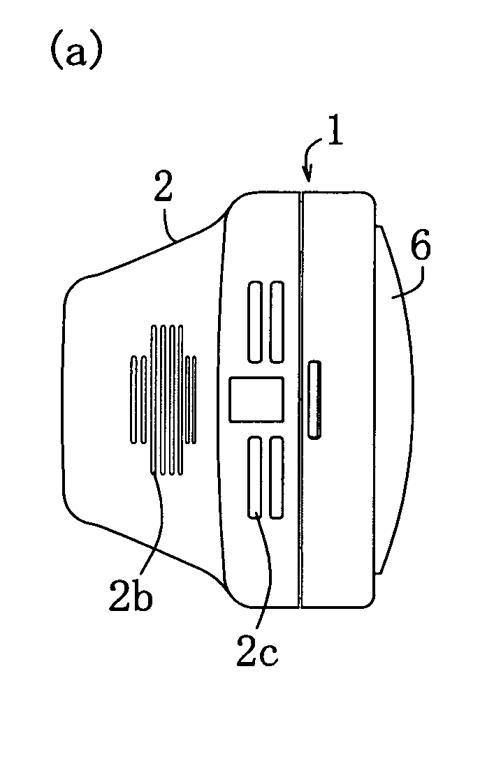
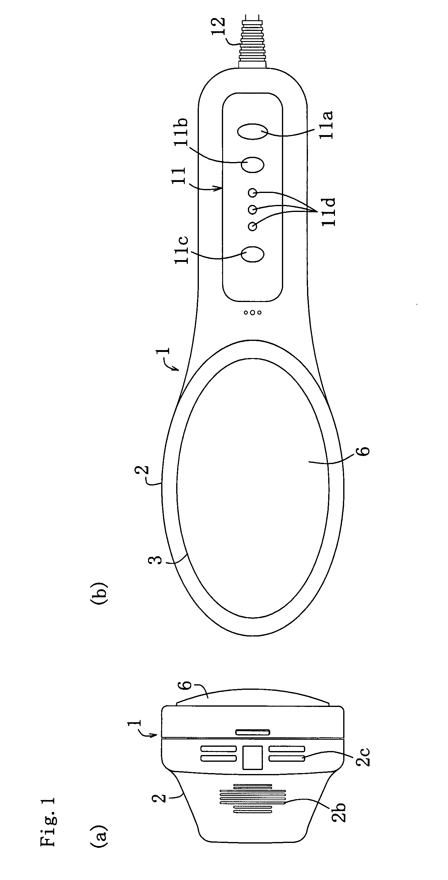
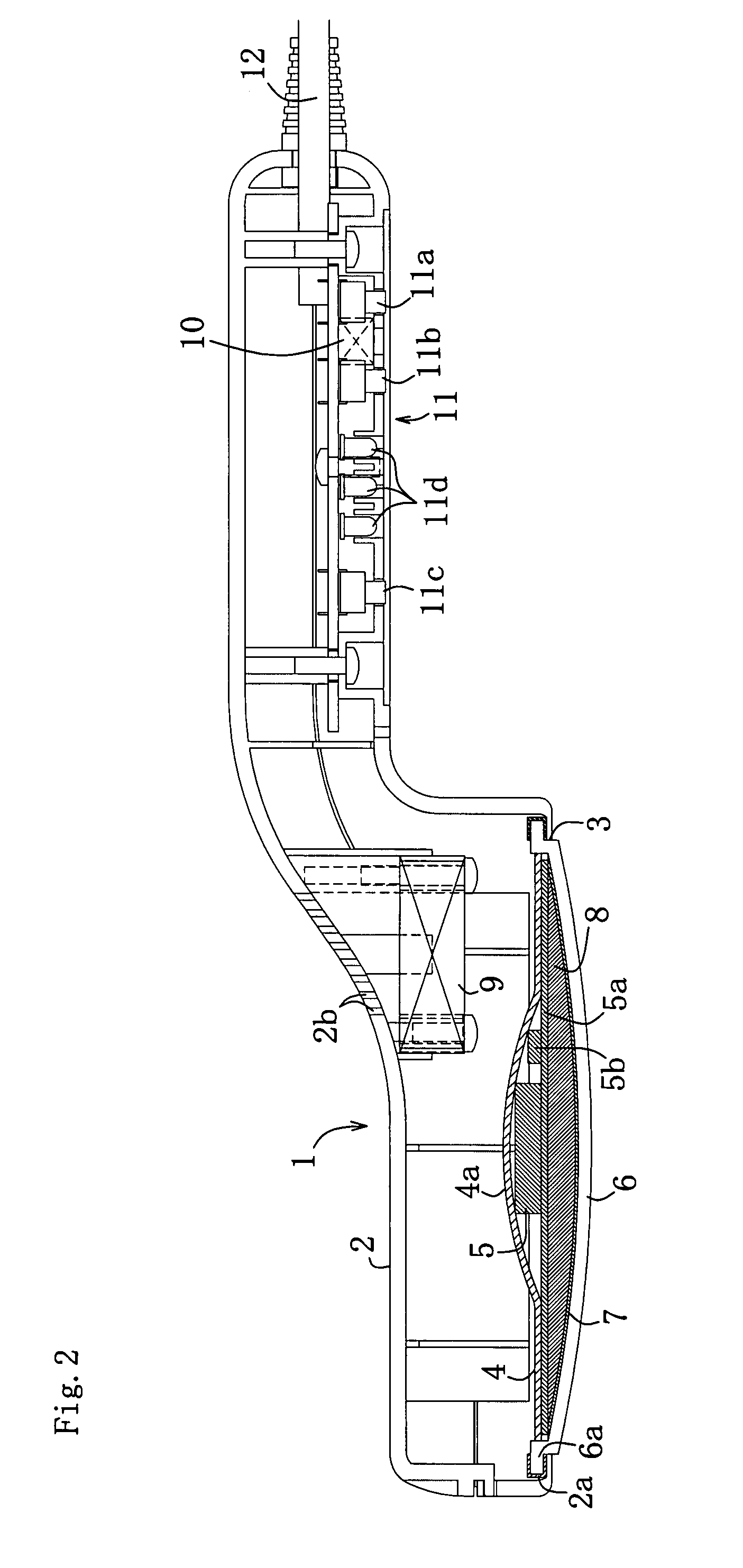
[0032]As shown in FIGS. 1 to 3, a flat iron-like moxibustion device 1 of the first embodiment has a flat iron-like main body 2 that is substantially in the form of a scoop in a plan view and an oval opening 3 that is formed at a front part of the main body 2. Inside the opening 3, a heat insulating plate 4 having a shape and a size that are substantially the same as those of the opening 3 in a plan view and a recess 4a formed at a central part is provided as being fixed to the opening 3, and a heater 5 having a flat plate-like heat generation surface 5a having a shape that is substantially the same as that of the opening 3 in a plan view and a size that is a little smaller than the opening 3 is housed in the recess 4a of the heat insulating plate, the heat generating surface 5a being disposed at a front surface of the heat insulating plate 4. Denoted by 5b is a thermistor provided in the heater 5.

[0...


PUM


Abstract

A flat iron-like moxibustion device provided with a flat iron-like main body 2, a heater 5, a dome-like transparent glass cover 6 an outwardly curved outer surface that is brought into contact with a human body and an inwardly curved inner surface on which fine irregularity 6b is formed, a far infrared ray radiation layer 7 coated on the inner surface of the glass cover 6 on which fine irregularity 6b is formed, and a clay-like far infrared ray radiation material 8 filled into the inside of the glass cover 6 as being in close contact with the far infrared ray radiation layer 7, the moxibustion device being capable of substantially uniform far infrared ray radiation and having an excellent appearance.

Description

TECHNICAL FIELD[0001]This invention relates to a moxibustion device in the form of a flat iron for performing warming and far infrared ray irradiation of a human body part.RELATED ART[0002]As a moxibustion device in the form of a flat iron for performing warming and far infrared ray irradiation of a human body part, the one disclosed in Patent Publication 1 (International Publication No. WO2004 / 075986A1) has been known. Patent Publication 1 discloses a flat iron type moxibustion device that generates a far infrared ray by heating a far infrared ray radiation material containing a radon-generating rare native element or two or more of tourmaline ore, carbon, and a radon-generating rare native element and brings the far infrared ray to a deep part of a human body. Disclosed in FIGS. 1 and 2 of Patent Publication 1 is a structure wherein a far infrared ray radiation layer formed of a tourmaline ore layer, a carbon layer, and a radon-generating rare native element layer is laminated on ...

Claims


Application Information

Patent Timeline
IPC IPC(8): A61M35/00A61F7/00
CPCA61F7/007A61F2007/0086A61F2007/0249A61N2005/066A61N2005/007A61N2005/0644A61N5/0613
Inventor YASUHIRO, SAKAMOTO
Owner SUPER ONNETABU
Learn More