Catheter with bendable tip

Active Publication Date: 2009-12-10
BIOSENSE WEBSTER INC
View PDF99 Cites 186 Cited by
  • Summary
  • Abstract
  • Description
  • Claims
  • Application Information

AI Technical Summary

Benefits of technology

[0005]The embodiments of the present invention that are described hereinbelow provide a novel design of an invasive probe, such as a catheter. The probe comprises a flexible insertion tube, having a distal end for insertion into a body cavity of a patient. The dis

Problems solved by technology

Excessive pressure, however, may cause undesired damage t

Method used


Image

  • Catheter with bendable tip
  • Catheter with bendable tip
  • Catheter with bendable tip

Examples


Embodiment Construction

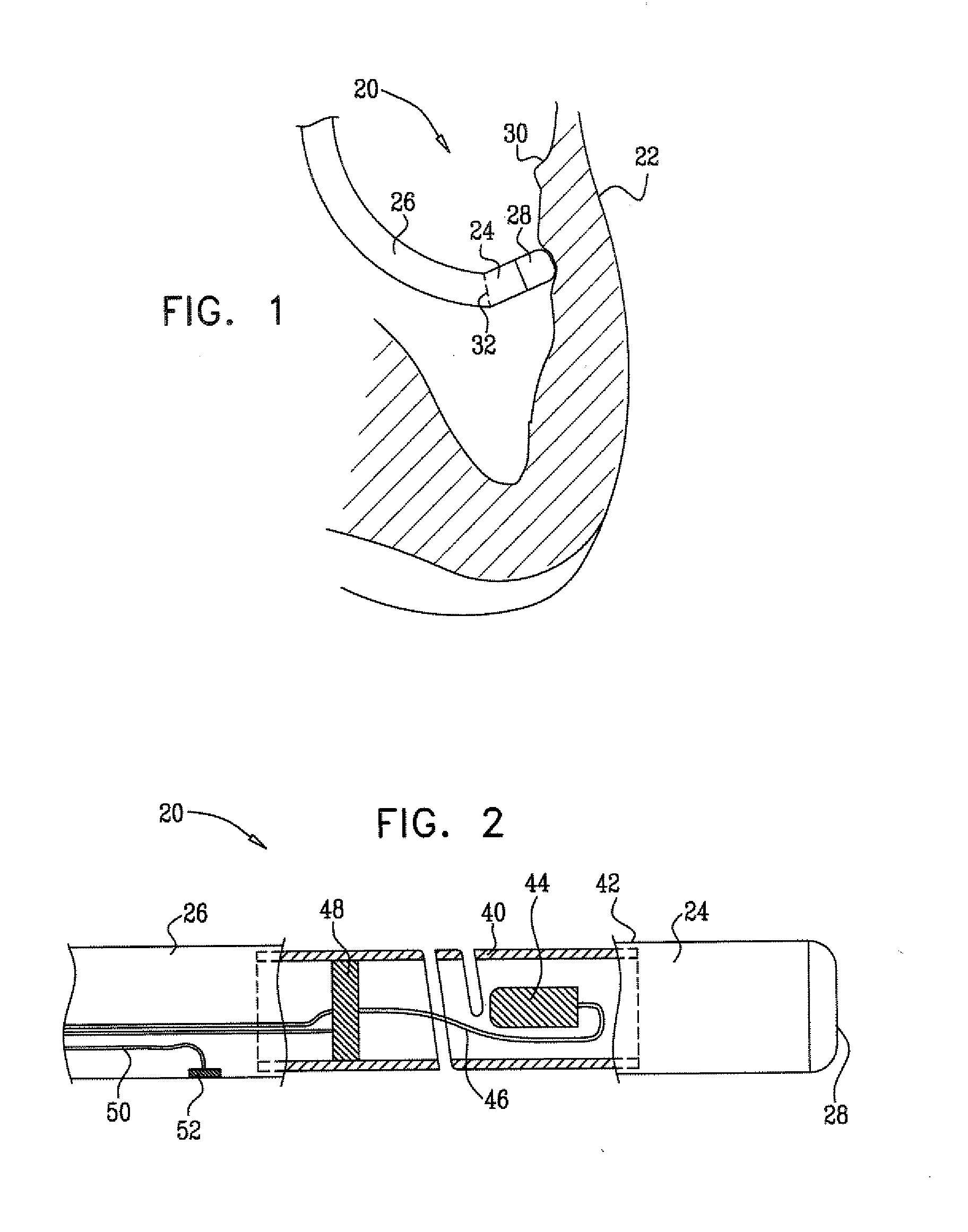
[0027]FIG. 1 is a schematic sectional view of a chamber of a heart 22, showing an insertion tube 26 of a catheter 20 inside the heart, in accordance with an embodiment of the present invention. The catheter is typically inserted into the heart percutaneously through a blood vessel, such as the vena cava or the aorta. An electrode 28 on a distal tip 24 of the catheter engages endocardial tissue 30. Pressure exerted by the distal tip against the endocardium deforms the endocardial tissue locally, so that electrode 28 contacts the tissue over a relatively large area. In the pictured example, the electrode engages the endocardium at an angle, rather than head-on. Distal tip 24 therefore bends at an elastic joint 32 relative to the insertion tube of the catheter. The bend facilitates optimal contact between the electrode and the endocardial tissue.

[0028]Because of the elastic quality of joint 32, the angle of bending of the joint is proportional to the pressure exerted by tissue 30 on di...


PUM

PropertyMeasurementUnit
Angleaaaaaaaaaa
Angleaaaaaaaaaa
Pressureaaaaaaaaaa

Abstract

A medical probe includes a flexible insertion tube, having a distal end for insertion into a body cavity of a patient, and a distal tip, which is disposed at the distal end of the insertion tube and is configured to be brought into contact with tissue in the body cavity. A coupling member couples the distal tip to the distal end of the insertion tube and includes a tubular piece of an elastic material having a helical cut therethrough along a portion of a length of the piece.

Description

FIELD OF THE INVENTION[0001]The present invention relates generally to invasive medical devices, and specifically to the construction of probes for insertion into body organs.BACKGROUND OF THE INVENTION[0002]In some diagnostic and therapeutic techniques, a catheter is inserted into a chamber of the heart and brought into contact with the inner heart wall. In such procedures, it is generally important that the distal tip of the catheter engages the endocardium with sufficient pressure to ensure good contact. Excessive pressure, however, may cause undesired damage to the heart tissue and even perforation of the heart wall.[0003]For example, in intracardiac radio-frequency (RF) ablation, a catheter having an electrode at its distal tip is inserted through the patient's vascular system into a chamber of the heart. The electrode is brought into contact with a site (or sites) on the endocardium, and RF energy is applied through the catheter to the electrode in order to ablate the heart ti...

Claims


Application Information

Patent Timeline
IPC IPC(8): A61B18/18A61B5/06B23P11/00A61M25/01
CPCA61B18/1492A61B2019/4857A61M25/0082Y10T29/49826A61B5/05A61B18/14A61M2025/0081A61B5/062A61B5/6851A61B5/6852A61B17/00234A61B34/20A61B2017/00243A61B2017/00309A61B2017/00526A61B2017/00862A61B2018/00357A61B2034/2051A61B2090/0811
Inventor GOVARI, ASSAFALTMANN, ANDRES CLAUDIOGARCIA, ARIEL
Owner BIOSENSE WEBSTER INC
Why Eureka
Try Eureka