Vision-based automated landing system for unmanned aerial vehicles

an automated landing and drone technology, applied in the direction of vehicle position/course/altitude control, process and machine control, instruments, etc., can solve the problems of burdensome use, damage to the drone, and high training requirements of pilots, so as to achieve the effect of safe landing of the dron

Inactive Publication Date: 2009-12-10
21ST CENTURY SYST
View PDF0 Cites 102 Cited by
  • Summary
  • Abstract
  • Description
  • Claims
  • Application Information

AI Technical Summary

Benefits of technology

[0010]The present invention discloses vision-based automated systems and methods for landing unmanned aerial vehicles. The system of the invention includes one or more UAVs, and one or more targets, of known geometry, positioned at one or more intended landing locations. The system further includes one or more sensors coupled to each UAV, such that at least one sensor is aligned with the direction of movement of the UAV, and captures one or more images in the direction of movement of the UAV. The system further includes at least one processor-based device, which determines the visual distortion of at least one target visible in one or more of the captured images as a function of the UAV's current position. This processor-based device calculates the UAV's current glideslope and lineup angle, and adjusts the current glideslope and alignment of the UAV to an intended glideslope and lineup angle, so as to safely land the UAV.

Problems solved by technology

UAVs have become increasingly popular for use in support of military operations, but the logistical complexity of UAV control, and the resultant cost, often makes their use burdensome.
Second, larger UAVs require highly trained pilots for takeoff and landing.
While micro and small UAVs can usually land in any open area at a non-prepared airfield, infrequent practice of UAV landings often results in hard or inexpert landings, which can damage the UAV.
GPS and altimeter-based systems are sufficient for establishing the aircraft in a landing pattern and beginning the approach descent, but the actual touchdown control is less than optimal.
Pitot-static systems, which use pressure-sensitive instruments (e.g. air pressure-sensitive instruments) to calculate the aircraft's airspeed and altitude, are generally more accurate than GPS-based systems, but are susceptible to similar problems—changes in ambient air pressure during the flight can affect altitude measurements.
An off-site landing can easily damage the aircraft when working on an unprepared landing strip or in an urban area.
These are simple for the operator to use and have a high rate of survivability.
The stall causes the aircraft to lose forward speed and drop to the ground.
A major disadvantage, however, is that this system is not portable to many other UAVs.
Larger, heavier aircraft create greater kinetic energy in a stall and would most likely suffer significant airframe damage if they attempted this sort of landing.
Their primary disadvantage is that they require substantial ground-based hardware, which makes them impractical for use with small and micro UAVs.
The use of ground-based hardware also increases their logistics footprint for larger UAVs, which may reduce their practicality in expeditionary warfare.
However, it is expensive and requires accurate human pilot directed adjustment to effect the proper glideslope, so it would not be practical to use it for most UAV operations.

Method used


Image

  • Vision-based automated landing system for unmanned aerial vehicles
  • Vision-based automated landing system for unmanned aerial vehicles
  • Vision-based automated landing system for unmanned aerial vehicles

Examples


Embodiment Construction

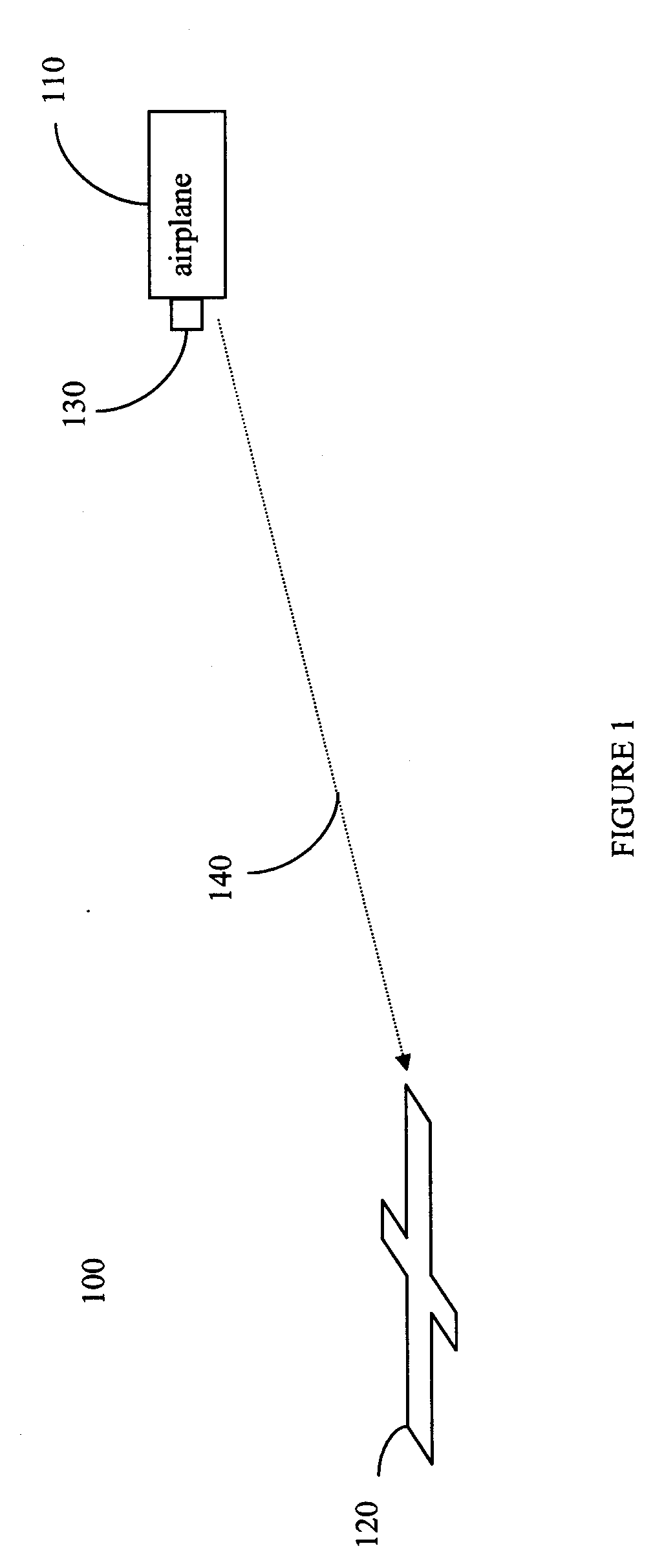
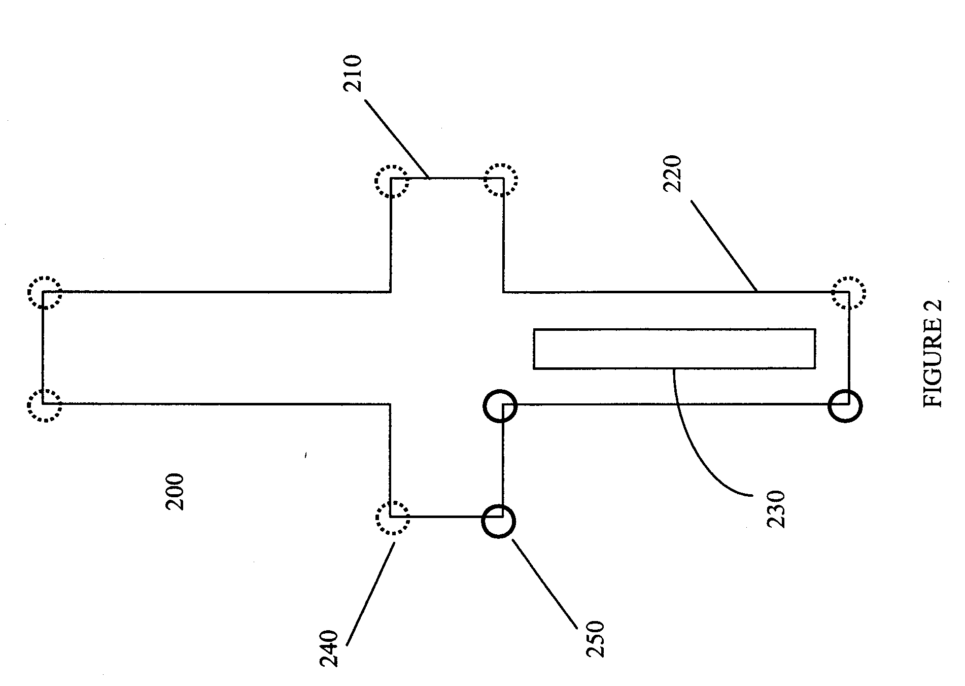
[0022]The present invention provides a vision-based automated system for landing UAVs, as shown in FIG. 1. The system 100 includes a UAV 110, which may be any micro, small, or large UAV. The system of the invention also includes one or more targets 120 positioned at one or more intended landing locations. A target must be of a known geometry and possess a minimum of three salient reference points (known hereinafter as “signature corners”). Signature corners are any reference points which can be used to regenerate the shape of an object. Examples of targets 120 may include, but are not limited to, runways, taxiways, buildings, or the entire airfield. In a preferred embodiment, the target 120 is a bilaterally symmetric cross.

[0023]The placement of the target 120 at the intended landing location may be permanent or fixed (i.e. removable). In one embodiment of the invention, the target 120 may be painted on a runway or other landing site. In another embodiment, the target 120 may be fix...


PUM


Abstract

The invention relates generally to the control and landing of unmanned aerial vehicles. More specifically, the invention relates to systems, methods, devices, and computer readable media for landing unmanned aerial vehicles using sensor input and image processing techniques.

Description

CROSS-REFERENCE TO RELATED APPLICATIONS[0001]This application claims the benefit under 35 U.S.C. § 119(e) of U.S. Provisional Application No. 61 / 043,360, filed Apr. 8, 2008, the entirety of which is incorporated herein by reference.FIELD OF THE INVENTION[0002]The present invention relates generally to the control and landing of unmanned aerial vehicles. More specifically, the present invention relates to systems, methods, devices, and computer readable media for landing unmanned aerial vehicles using sensor input and image processing techniques.BACKGROUND OF THE INVENTION[0003]Unmanned aerial vehicles (UAVs) are aircraft that fly without onboard pilots. They rely on complete or partial automation for control during their flight. UAVs have become increasingly popular for use in support of military operations, but the logistical complexity of UAV control, and the resultant cost, often makes their use burdensome. First, the soldiers who fly UAVs will always have other duties or circums...

Claims


Application Information

Patent Timeline
Patent Type & Authority Applications(United States)
IPC IPC(8): G05D1/00G06G7/70B64C19/00
CPCG05D1/0676
Inventor BLENKHORN, KEVIN P.O'HARA, STEPHEN V.
Owner 21ST CENTURY SYST
Why Eureka
Try Eureka