
System and method of an in-band modem for data communications over digital wireless communication networks

a data communication and in-band modem technology, applied in the field of system and method, can solve the problems of increasing the complexity of the data communication system, the priority of fast data transmission is not always realistic, and the new application development tends to outpace the evolution of the network

Active Publication Date: 2009-12-10
QUALCOMM INC
View PDF99 Cites 42 Cited by
  • Summary
  • Abstract
  • Description
  • Claims
  • Application Information

AI Technical Summary

Benefits of technology

[0030]In another embodiment, a system for communicating data over an in-band communication system from a vehicle containing an in-vehicle system (IVS) to a public safety answering point (PSAP) comprises one or more sensors located in the IVS for providing IVS sensor data, an IVS transmitter located in the IVS for transmitting the IVS sensor data, a PSAP receiver located in the PSAP for receiving the IVS sensor data, a PSAP transmitter located in the PSAP for transmitting PSAP command data, an IVS receiver located in the IVS for receiving the PSAP command data; wherein the IVS transmitter comprises an IVS message formatter for formatting the IVS sensor data and producing an IVS message, an IVS processor for processing the IVS message and producing a plurality of IVS shaped pulse signals, an IVS speech encoder for encoding the IVS shaped pulse signals and producing an IVS encoded signal, an IVS synchronization generator for generating an IVS synchronization signal, and an IVS transmit controller for transmitting a sequence of IVS synchronization signals and IVS messages; wherein the PSAP receiver comprises a PSAP detector for detecting the IVS synchronization signal and producing a PSAP sync flag, a PSAP demodulator for demodulating the IVS message and producing a received IVS message; wherein the PSAP transmitter comprises a PSAP message formatter for formatting the PSAP command data and producing a PSAP command message, a PSAP processor for processing the PSAP command message and producing a plurality of PSAP shaped pulse signals, a PSAP speech encoder for encoding the PSAP shaped pulse signals and producing a PSAP encoded signal, a PSAP synchronization generator for generating a PSAP synchronization signal, and a PSAP transmit controller for transmitting a sequence of PSAP synchronization signals and PSAP command messages; wherein the IVS receiver comprises an IVS detector for detecting the PSAP synchronization signal and producing an IVS sync flag, and an IVS demodulator for demodulating the PSAP messages and producing a received PSAP message.

Problems solved by technology

New applications being developed tend to outpace the evolution of the networks and may require upgrades to the communication system modulation schemes and protocols.
In some remote geographical areas only speech services may be available due to a lack of infrastructure support for advanced data services in the system.
In these emergency application examples, fast data transfer is a priority but not always realistic especially when advanced data services are not available at the user terminal.
Previous techniques have provided solutions to transmit data through a speech codec, but these solutions are only able to support low data rate transfers due to the coding inefficiencies incurred when trying to encode a non-speech signal with a vocoder.
Signals which do not contain periodic or noise-like characteristics are not effectively encoded by the vocoder and may result in severe distortion at the decoded output in some cases.
Most vocoders are unable to efficiently and effectively encode such signals.
Using predetermined frequency tones to transfer data through speech codecs, especially at higher data rates, is unreliable due to the vocoders employed in the systems.
The limited parameters are insufficient to effectively model the tone signals.
This affects the detection accuracy and results in the need to add complex schemes to minimize the data errors which in turn further reduces the overall data rate of the communication system.

Method used


Image

  • System and method of an in-band modem for data communications over digital wireless communication networks
  • System and method of an in-band modem for data communications over digital wireless communication networks
  • System and method of an in-band modem for data communications over digital wireless communication networks

Examples


Embodiment Construction

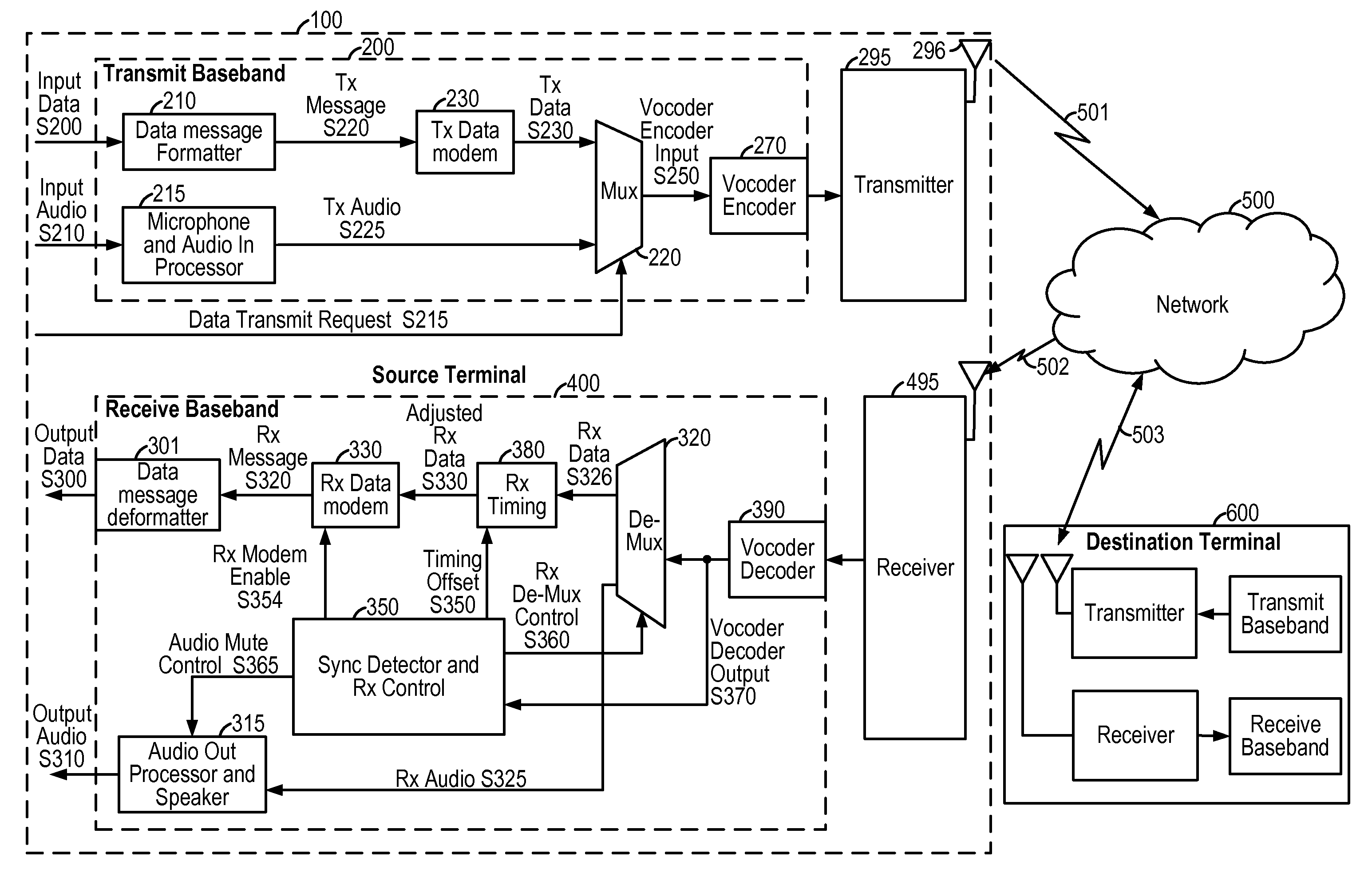
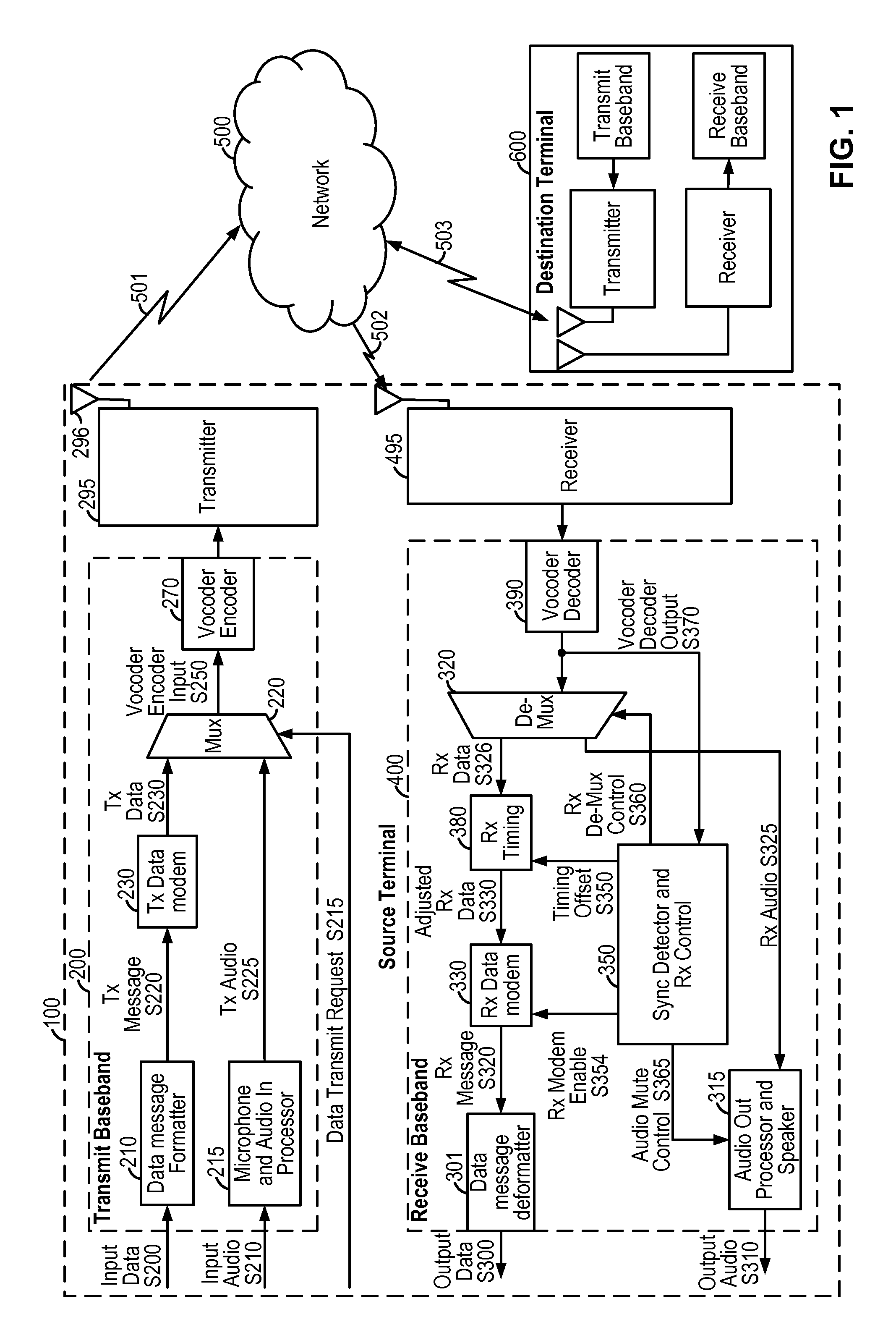
[0075]FIG. 1 shows an embodiment of an in-band data communication system as might be implemented within a wireless source terminal 100. The source terminal 100 communicates with the destination terminal 600 through the communication channels 501 and 502, network 500, and communication channel 503. Examples of suitable wireless communication systems include cellular telephone systems operating in accordance with Global System for Mobile Communication (GSM), Third Generation Partnership Project Universal Mobile Telecommunication System (3GPP UMTS), Third Generation Partnership Project 2 Code Division Multiple Access (3GPP2 CDMA), Time Division Synchronous Code Division Multiple Access (TD-SCDMA), and Worldwide Interoperability for Microwave Access (WiMAX) standards. One skilled in the art will recognize that the techniques described herein may be equally applied to an in-band data communication system that does not involve a wireless channel. The communication network 500 includes any...


PUM


Abstract

A system is provided for transmitting information through a speech codec (in-band) such as found in a wireless communication network. A modulator transforms the data into a spectrally noise-like signal based on the mapping of a shaped pulse to predetermined positions within a modulation frame, and the signal is efficiently encoded by a speech codec. A synchronization sequence provides modulation frame timing at the receiver and is detected based on analysis of a correlation peak pattern. A request / response protocol provides reliable transfer of data using message redundancy, retransmission, and / or robust modulation modes dependent on the communication channel conditions.

Description

CLAIM OF PRIORITY[0001]A claim of priority is made to the following U.S. Provisional Applications: No. 61 / 059,179 entitled “ROBUST SIGNAL FOR DATA TRANSMISSION OVER IN-BAND VOICE MODEM IN DIGITAL CELLULAR SYSTEMS” filed Jun. 5, 2008, and assigned to the assignee hereof and hereby expressly incorporated by reference herein; and No. 61 / 087,923 entitled “SYSTEM AND METHOD OF AN IN-BAND MODEM FOR DATA COMMUNICATIONS OVER DIGITAL WIRELESS (OR CELLULAR) COMMUNICATION NETWORKS” filed Aug. 11, 2009, and assigned to the assignee hereof and hereby expressly incorporated by reference herein; and No. 61 / 093,657 entitled “SYSTEM AND METHOD OF AN IN-BAND MODEM FOR DATA COMMUNICATIONS OVER DIGITAL WIRELESS (OR CELLULAR) COMMUNICATION NETWORKS” filed Sep. 2, 2008, and assigned to the assignee hereof and hereby expressly incorporated by reference herein; and No. 61 / 122,997 entitled “SYSTEM AND METHOD OF AN IN-BAND MODEM FOR DATA COMMUNICATIONS OVER DIGITAL WIRELESS (OR CELLULAR) COMMUNICATION NETWOR...

Claims


Application Information

Patent Timeline
Patent Type & Authority Applications(United States)
IPC IPC(8): G10L21/00G10L25/93H04L12/66
CPCG10L19/018H04J3/0611G10L19/00G10L19/008H04L25/4902H04L7/027H04W56/00H04J3/06
Inventor PIETSCH, CHRISTIANFRANK, GEORGSGRAJA, CHRISTIANHUANG, PENGJUNJOETTEN, CHRISTOPH A.WERNER, MARC W.GRANZOW, WOLFGANG
Owner QUALCOMM INC
Learn More