Blowby gas returning apparatus

a technology of blowby gas and apparatus, which is applied in the direction of mechanical apparatus, machines/engines, and non-fuel substance addition to fuel, etc., can solve problems affecting engine operation, and achieve the effect of increasing intake resistance and increasing boost pressur

Active Publication Date: 2009-12-17
AISAN IND CO LTD
View PDF4 Cites 74 Cited by
  • Summary
  • Abstract
  • Description
  • Claims
  • Application Information

AI Technical Summary

Benefits of technology

[0007]According to the present invention, it is possible to return blowby gas to an engine without increasing intake resistance during operation of a turbocharger and to increase a blowby gas returning flow rate according to an increase in boost pressure.

Problems solved by technology

Furthermore, the increased filter density will increase intake resistance in the intake passage, resulting in a problem that affects engine operation.

Method used


Image

  • Blowby gas returning apparatus
  • Blowby gas returning apparatus
  • Blowby gas returning apparatus

Examples


first embodiment

[0017]A detailed description of a first preferred embodiment of a blowby gas returning apparatus embodying the present invention will now be given referring to the accompanying drawings.

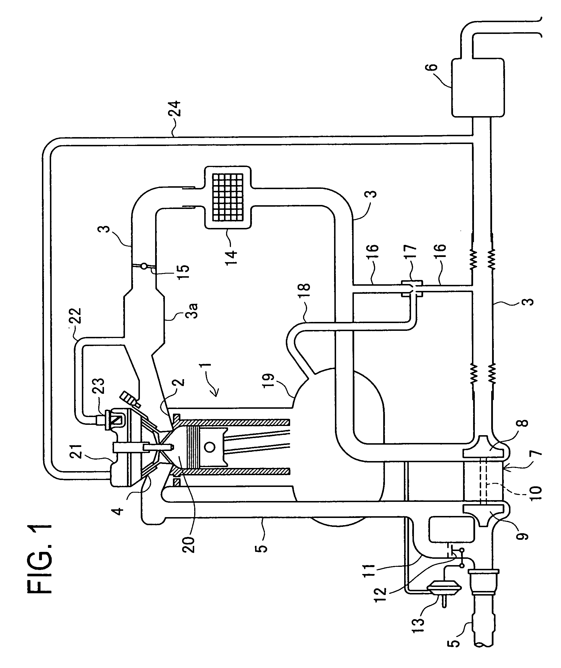
[0018]FIG. 1 is a schematic configuration view of an engine system including a blowby gas returning apparatus in this embodiment. This engine system includes a reciprocal engine 1 having an intake port 2 connected to an intake passage 3 and an exhaust port 4 connected to an exhaust passage 5. At an entrance of the intake passage 3, an air cleaner 6 is placed. A turbocharger 7 is placed between the intake passage 3 downstream of the air cleaner 6 and the exhaust passage 5 to increase intake pressure in the intake passage 3.

[0019]The turbocharger 7 includes a compressor 8 disposed in the intake passage 3, a turbine 9 disposed in the exhaust passage 5, and a rotation shaft 10 connecting the compressor 8 and the turbine 9 to integrally rotate them. The turbocharger 7 is arranged such that the turbine 9 i...

second embodiment

[0030]Next, a blowby gas returning apparatus in a second embodiment according to the present invention will now be explained with reference to the accompanying drawings.

[0031]In each of the following embodiments, the same or similar components to those in the first embodiment are given the same reference signs and respective details are not repeatedly explained. The following description is made with a focus on differences from the first embodiment.

[0032]FIG. 4 is a schematic configuration view of an engine system including the blowby gas returning apparatus in this embodiment. This embodiment differs in configuration from the first embodiment in that a vacuum switching valve (VSV) 25 is placed in the intake bypass passage 16 and controlled by an electronic control unit (ECU) 26 according to an operating condition of the engine 1. Herein, the ECU 26 receives detection values of an engine rotation speed, intake pressure, etc. from various sensors (not shown) attached to the engine 1 ...

third embodiment

[0037]A blowby gas returning apparatus in a third embodiment according to the present invention will now be explained in detail with reference to the accompanying drawing.

[0038]FIG. 6 is a schematic configuration view of an engine system including the blowby gas returning apparatus in this embodiment. This embodiment differs in configuration from the second embodiment in that the first blowby gas returning passage 18 is also provided with a PCV valve 27. Specifically, the crank case 19 is provided with the PCV valve 27 is provided at the entrance of the first blowby gas returning passage 18.

[0039]According to the blowby gas returning apparatus in this embodiment, the PCV valve 27 adjusts the flow rate of blowby gas allowed to flow from the crank case 19 into the first blowby gas returning passage 18 toward the jet pump 17. This makes it possible to prevent excessive blowby gas from returning to the combustion chamber 20 through the first blowby gas returning passage 18. Other operat...


PUM


Abstract

A blowby gas returning apparatus is mounted in an engine provided with a turbocharger in an intake passage and provided with a blowby gas returning passage for flowing blowby gas generated in the engine to return to the engine. This apparatus comprises an intake bypass passage connecting an upstream side and a downstream side of the intake passage with respect to the turbocharger, and a jet pump for generating negative pressure in the intake bypass passage. An exit of the first blowby gas returning passage is connected to the intake bypass passage through the jet pump. The apparatus further includes a second blowby gas returning passage connecting the intake passage downstream of the throttle valve to a head cover. In the head cover, a PCV valve is placed at an entrance of the second blowby gas returning passage.

Description

CROSS-REFERENCE TO RELATED APPLICATIONS [0001]This application is based upon and claims the benefit of priority from each of the prior Japanese Patent Application No. 2008-157766 filed on Jun. 17, 2008, the entire contents of which are incorporated herein by reference.TECHNICAL FIELD [0002]The present invention relates to a blowby gas returning apparatus to be mounted in an engine provided with a turbocharger or supercharger in an intake passage to return blowby gas that occurs in the engine to the engine via the intake passage.BACKGROUND ART [0003]As this type of technique, heretofore, there are known techniques disclosed in JP2008-95528A, JP2008-111422A, JP64(1989)-24106A, JP63(1988)-158516U, and JP56(1981)-99046U. Particularly, a blowby gas returning apparatus disclosed in JP2008-95528A is arranged such that a turbocharger is placed in an intake passage of an engine. A first blowby gas returning passage is placed between the intake passage downstream of the turbocharger and a cra...

Claims


Application Information

Patent Timeline
Patent Type & Authority Applications(United States)
IPC IPC(8): F02B25/06F02M25/07
CPCF01M13/022Y02T10/121F02M25/06F01M2013/027Y02T10/12
Inventor KONOHARA, HIROKAZU
Owner AISAN IND CO LTD
Why Eureka
Try Eureka