
Push-to-expand mandrel for stretch-wrap hand tool

Inactive Publication Date: 2009-12-17
ILLINOIS TOOL WORKS INC
View PDF0 Cites 33 Cited by
  • Summary
  • Abstract
  • Description
  • Claims
  • Application Information

AI Technical Summary

Benefits of technology

[0012]It is therefore an object of the present invention to provide a dispenser for film handling which reduces damage to film and which allows the coreless film roll to be fully unwound with reduced or eliminated waste of film.
[0013]It is therefore a further object of the present invention to provide a dispenser which can be easily inserted into a coreless roll with reduced or eliminated snagging and damaging of the film.
[0014]These and other objects are attained by providing a dispenser with a mandrel which expands radially in response to axial motion of an internal shaft, which includes cam elements, thereby moving the mandrel sections radially outward. The mandrel sections which expand radially outward against the internal diameter of a core or coreless film roll in response to the axial motion of an internal shaft can be implemented by at least two embodiments. The first embodiment uses a mandrel with a leaf-spring configuration in which the sections themselves expand uniformly outward. The second embodiment uses a mandrel with a collet-spring configuration. In either case, the mandrels are unlikely to damage the layer of film nearest the inside of the film roll at the edges.
[0015]Moreover, the mandrels can contract so that the mandrel can be removed from a coreless roll with a greatly reduced likelihood of damage. The shaft extension or retraction causes the mandrels of the dispenser to expand or contract uniformly and is a motion that typically does not interfere with the typical rotary motion of the dispenser during unwinding.

Problems solved by technology

In either case, the mandrels are unlikely to damage the layer of film nearest the inside of the film roll at the edges.

Method used


Image

  • Push-to-expand mandrel for stretch-wrap hand tool
  • Push-to-expand mandrel for stretch-wrap hand tool
  • Push-to-expand mandrel for stretch-wrap hand tool

Examples


Embodiment Construction

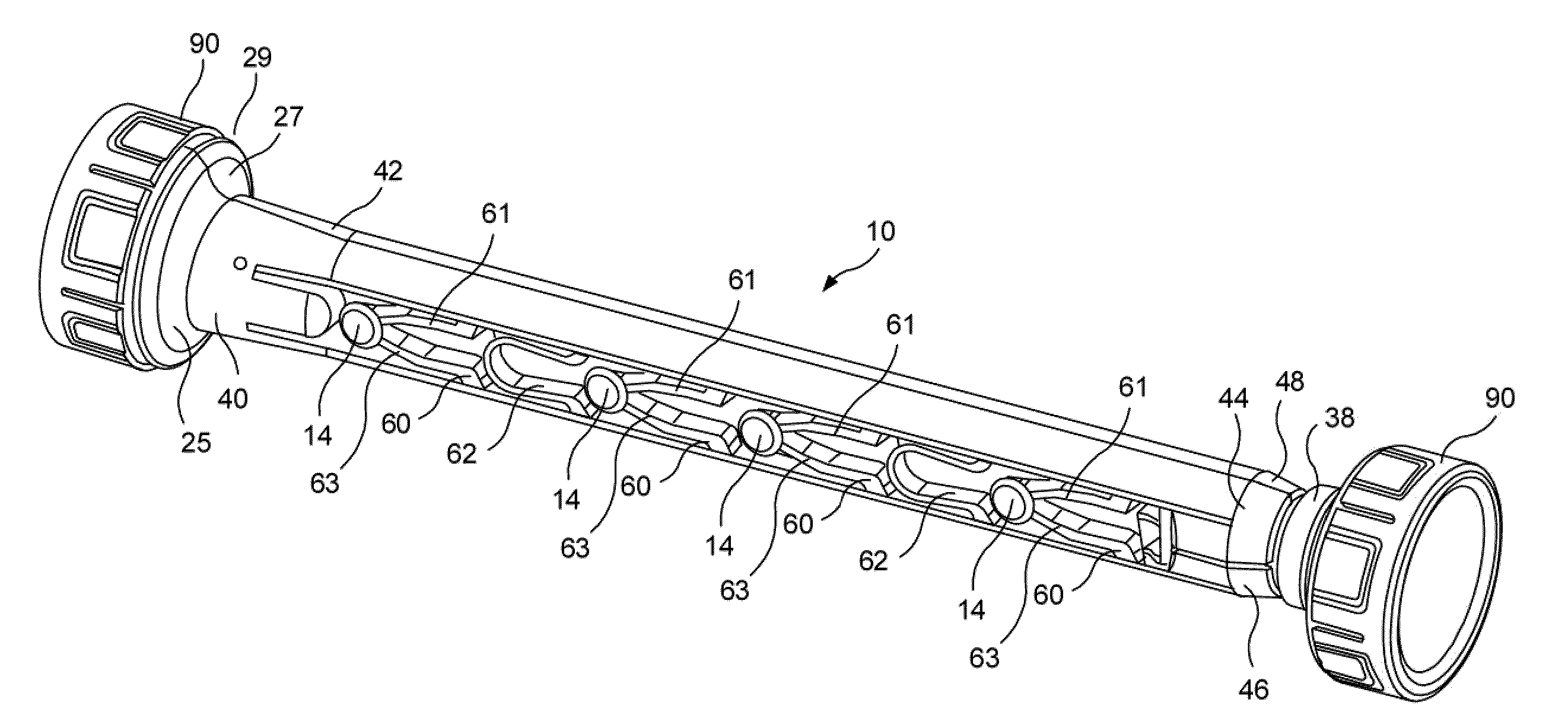
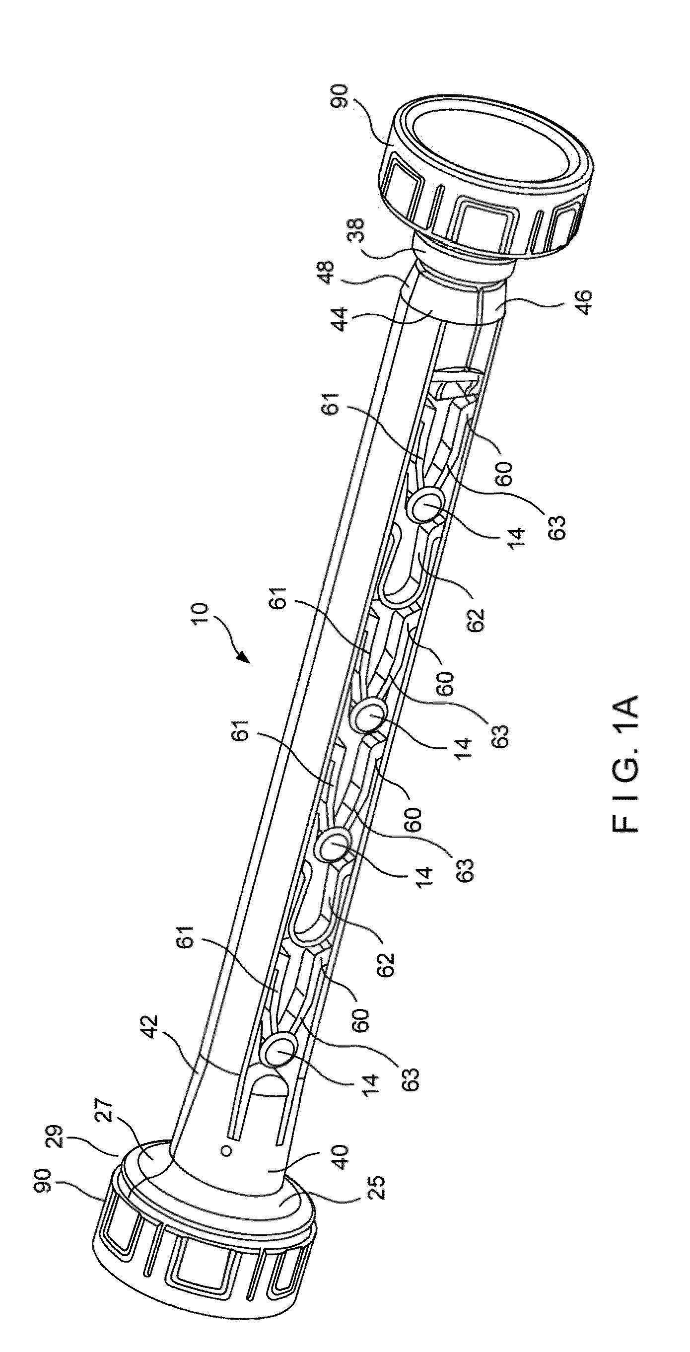
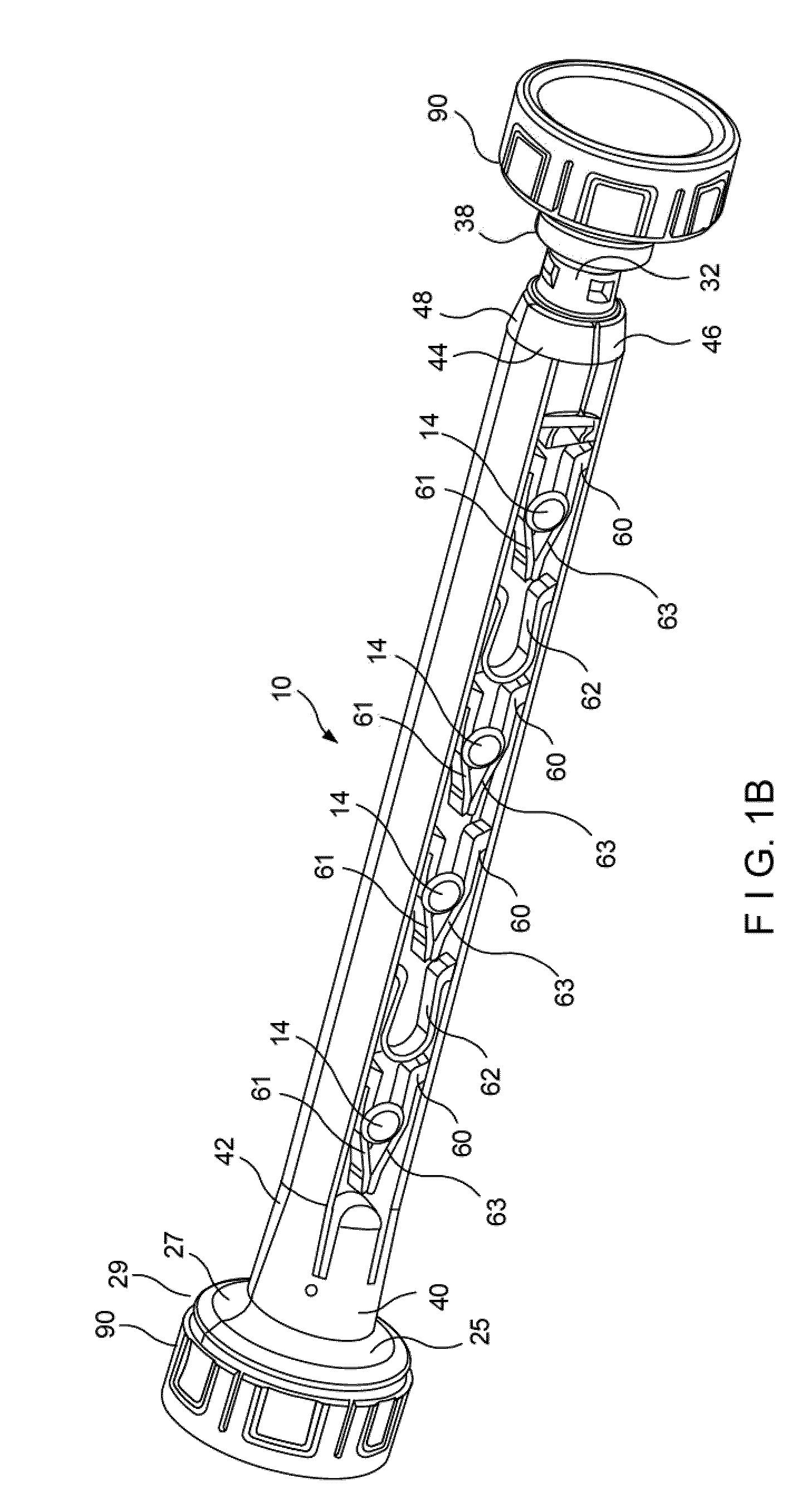
[0037]Referring now to the drawings in detail wherein like numerals indicate like elements throughout the several views, one sees that FIGS. 1A, 1B, 2, 3 and 4 are various views of a first embodiment of dispenser 10. Dispenser 10 includes a central shaft 12, with a square or rectangular cross section, with cam lugs 14 protruding from two opposing sides of central shaft 12. Cam lugs 14 can be integrally molded with central shaft or can be attached thereto. The cam lugs 14 include expanded or bulbous heads 15 which serve to slidingly engage the mandrels thereto. Central shaft 12 includes first end 16 and second end 18. First end 16 of shaft 12 includes a portion 32 of circular cross section and further includes longitudinal blind aperture 34 which receives longitudinal male portion or stem 36 of first cup 38 thereby holding cup 38 so that first cup 38 moves in concert with central shaft 12. First cup 38 can be replaced with an axially oriented handle 39 as illustrated in FIG. 17. Seco...


PUM

PropertyMeasurementUnit
Diameteraaaaaaaaaa
Radiusaaaaaaaaaa
Tensionaaaaaaaaaa

Abstract

The present disclosure relates to a dispenser for use with rolls of film material, particularly coreless rolls. The mandrels of the dispenser can move between a retracted position wherein the dispenser has a reduced diameter, such as for when the dispenser is being inserted into a roll of film, and an increased diameter, such as for when the film is being dispensed from the dispenser. The mandrels have sections which are joined by various spring configurations and are formed as being axially slidable with respect to a central shaft with lug elements. As the mandrel is slid along the central shaft, the lug elements deflect the spring configurations outwardly so as move the mandrels radially outwardly and increase the radius of the dispenser.

Description

[0001]This application claims priority under 35 U.S.C. §119(e) of provisional application Ser. No. 61 / 131,691 filed on Jun. 11, 2008, the contents of which are hereby incorporated by reference.BACKGROUND OF THE INVENTION[0002]1. Field of the Invention[0003]The present invention relates to a dispenser with a mandrel which can be radially expanded by a longitudinal pushing action in order to engage a roll of material, particularly stretch wrap material, more tightly.[0004]2. Description of the Prior Art[0005]In the prior art, there are many types of dispensers for an operator to hold a film roll and to apply tension on the film while hand wrapping a typical pallet load. Most of the commercial film rolls use paper cores on the internal diameter of the film roll, which helps to reinforce the roll from bending and to protect the film particularly toward the end of the roll. There are many different commercial types of dispenser mandrels and end cups used with the paper core rolls. Typica...

Claims


Application Information

Patent Timeline
IPC IPC(8): B65H75/24
CPCB65H75/242B65H2701/5122B65H2701/1752B65H2402/412B65H75/248
Inventor PIOTROWSKI, STANLEYMCMAHON, MICHAEL J.
Owner ILLINOIS TOOL WORKS INC
Learn More