

Power factor correction circuit
a power factor and circuit technology, applied in the direction of electric variable regulation, process and machine control, instruments, etc., can solve the problems of inability of related art to meet a new requirement, inability of related art to achieve a power factor correcting ratio specified by high frequency restrictions, etc., to achieve the effect of simple, inexpensive, and complying with level v of energy star
- Summary
- Abstract
- Description
- Claims
- Application Information
AI Technical Summary
Benefits of technology
Problems solved by technology
Method used
Image

Examples
embodiment 1
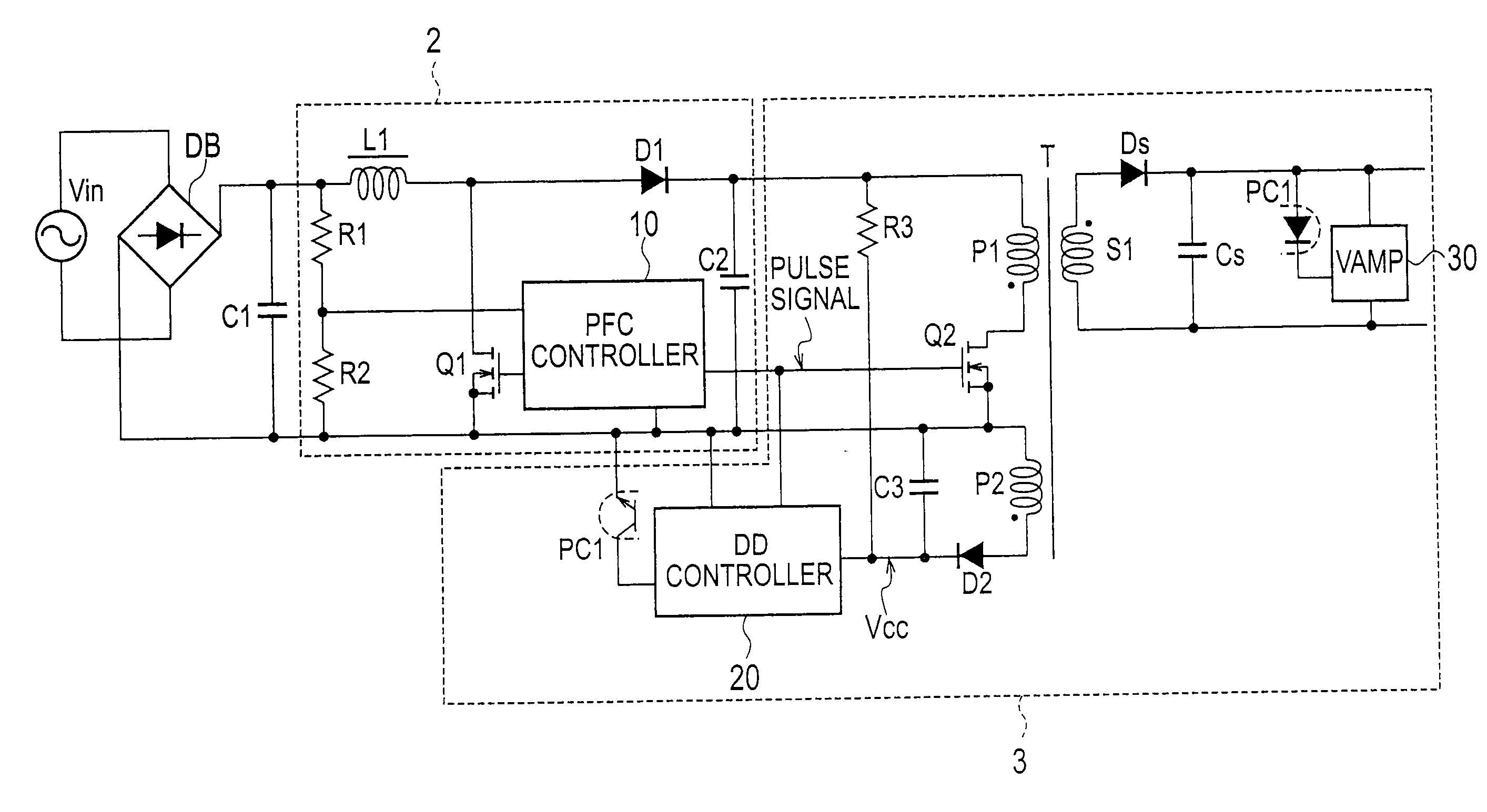
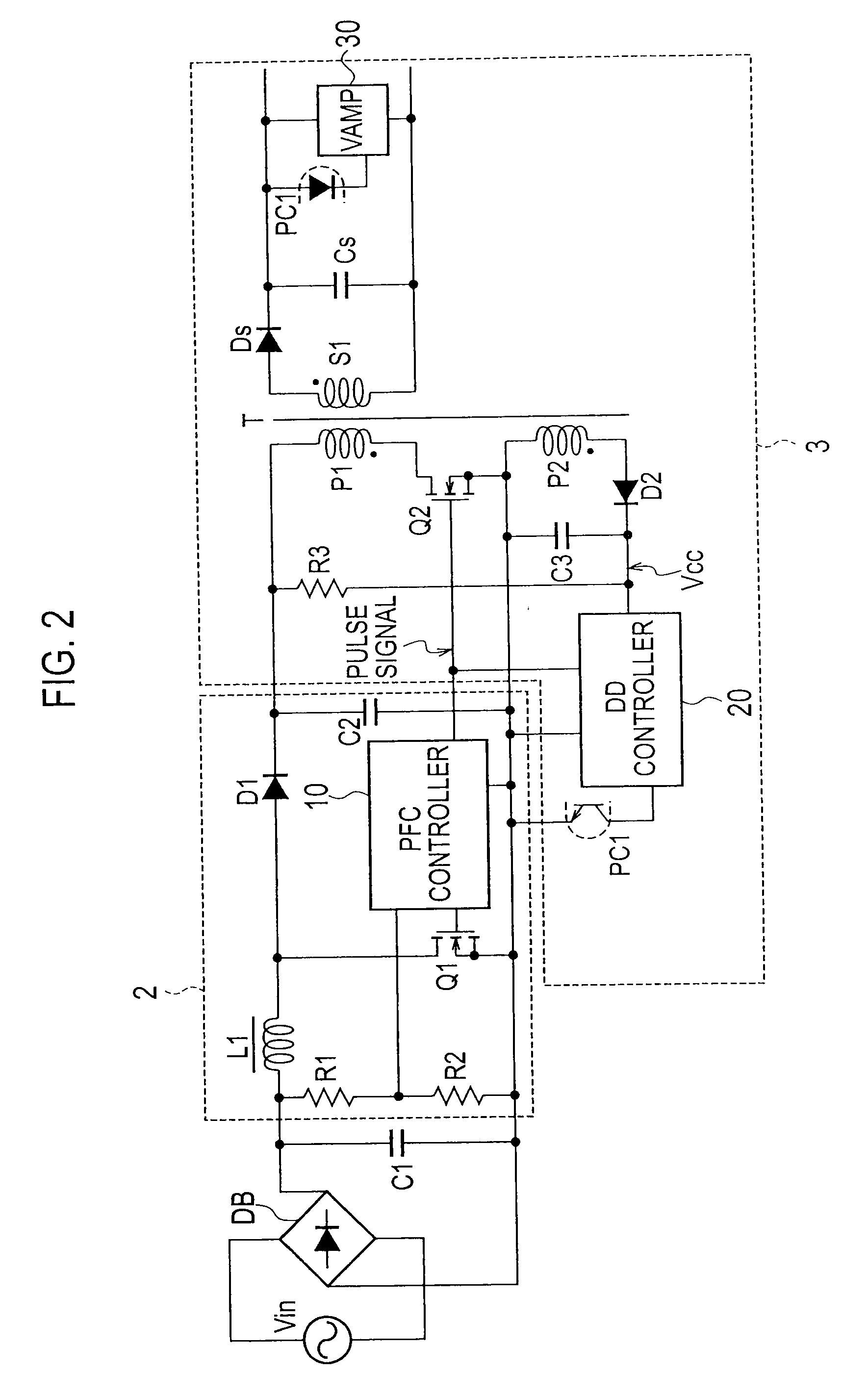
[0034]FIG. 2 is a circuit diagram illustrating an AC-DC converter including a power factor correction circuit according to Embodiment 1 of the present invention. The AC-DC converter includes a rectifier DB rectifying an AC input voltage from an AC power source Vin into a rectified voltage, a smoothing capacitor C1 connected to an output end of the rectifier DB, a power factor correction (PFC) circuit 2 stepping up the rectified voltage and correcting a power factor of the same, and a DC-DC converter 3 converting the stepped-up voltage from the power factor correction circuit 2 into a DC voltage and supplying the DC voltage to a load.
[0035]The DC-DC converter 3 has a series circuit including a primary winding P1 of a transformer T1 and a switching element Q2 made of a MOSFET, the series circuit being connected to a capacitor C2 of the power factor correction circuit 2. Both ends of a secondary winding S1 of the transformer T1 are connected to a series circuit including a diode Ds and...
embodiment 2
[0069]FIG. 10 is a circuit diagram illustrating the details of a PFC (power factor correction) controller 10b in a power factor correction circuit according to Embodiment 2. According to Embodiment 1 of FIG. 3, the power factor correction circuit 2 does not monitor a stepped-up voltage, and therefore, a step-up operation continues even if an AC input voltage becomes excessively high.
[0070]The present embodiment deals with such an excessively high AC input voltage by correcting the pulse width of a delay pulse signal so as to improve a step-up ratio and power factor for a PFC output voltage.
[0071]The PFC controller 10b according to Embodiment 2 illustrated in FIG. 10 includes, in addition to the components of the PFC controller 10 according to Embodiment 1 illustrated in FIG. 3, an additional circuit including resistors R14 to R18, a transistor Q9, and a diode D5. This additional circuit forms a corrector that corrects the pulse width of a delay pulse signal according to a PFC output...
embodiment 3
[0081]FIG. 13 is a circuit diagram illustrating the details of a PFC controller (power factor correction controller) in a power factor correction circuit according to Embodiment 3 of the present invention. The delay circuit 12 of Embodiment 1 includes the transistors Q7 and Q8. According to Embodiment 3, a delay circuit 13 includes a comparator CP1. The driver of Embodiment 1 for driving the switching element Q1 includes the transistors Q3 and Q4. According to Embodiment 3, a driver for driving a switching element Q1 includes MOSFETs Q3a and Q4a and an inverter INV.
[0082]In the delay circuit 13 of the present embodiment, connected between a gate side terminal of a switching element Q2 of a DD controller (DC-DC converter controller) 20 and a negative electrode terminal of a rectifier DB are an integrator having a resistor R13 and a capacitor C5 connected in series and also a series circuit of resistors R11 and R12.
[0083]A connection point of the resistors R11 and R12 is connected to ...
PUM
 Abstract
Description
Claims
Application Information