
Logical geographical and subscriber ONT subgroups in support of fiber-to-the-premises (FTTP) architecture

a technology of subscriber ont and fiber-to-the-premises, applied in the field of traditional networking products, can solve the problems of bandwidth constraints between the olt, limited throughput, and traditional methods of providing bandwidth throughout the premises, such as over coaxial cable (coax) using multimedia over coax

Inactive Publication Date: 2009-12-17
TELLABS VIENNA
View PDF6 Cites 22 Cited by
  • Summary
  • Abstract
  • Description
  • Claims
  • Application Information

AI Technical Summary

Problems solved by technology

There are traditional networking products that provide limited throughput due to hardware limitations.
However, this produces bandwidth constraints between the OLT and each Customer Premises Equipment (CPE) device connected to the ONT that is requesting bandwidth.
Moreover, traditional methods of providing bandwidth throughout a premises, such as over coaxial cable (COAX) using the Multimedia over Coax Alliance (MoCA) standard and over twisted pair cable (TP) (e.g., Category 1 cable (CAT-1), Category 5 cable (CAT-5), and Category 6 cable (CAT-6)) by Ethernet, are limited in the bandwidth they can provide.
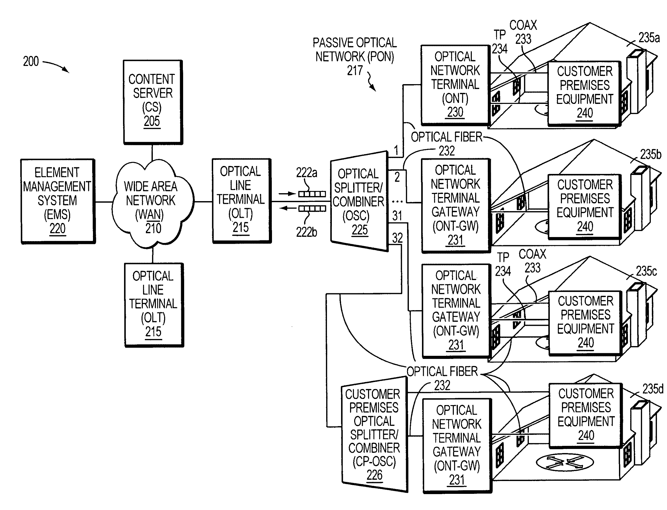
Further, an Element Management System (EMS) of the PON is generally not aware of the CPE devices in the network, such as in a home.
Therefore, if there are problems with CPE devices, a service provider may not know if the problem is associated with the ONT or a device connected to the ONT.
This can lead to added costs in sending a technician to the customer premises to diagnose the problem, which may turn out to be unnecessary, if the problem is, for example: a bad connection to a CPE device, a home router that is not connected or functioning properly, or another problem with a CPE device limited to customer equipment.

Method used


Image

  • Logical geographical and subscriber ONT subgroups in support of fiber-to-the-premises (FTTP) architecture
  • Logical geographical and subscriber ONT subgroups in support of fiber-to-the-premises (FTTP) architecture
  • Logical geographical and subscriber ONT subgroups in support of fiber-to-the-premises (FTTP) architecture

Examples


Embodiment Construction

[0015]A description of example embodiments of the invention follows.

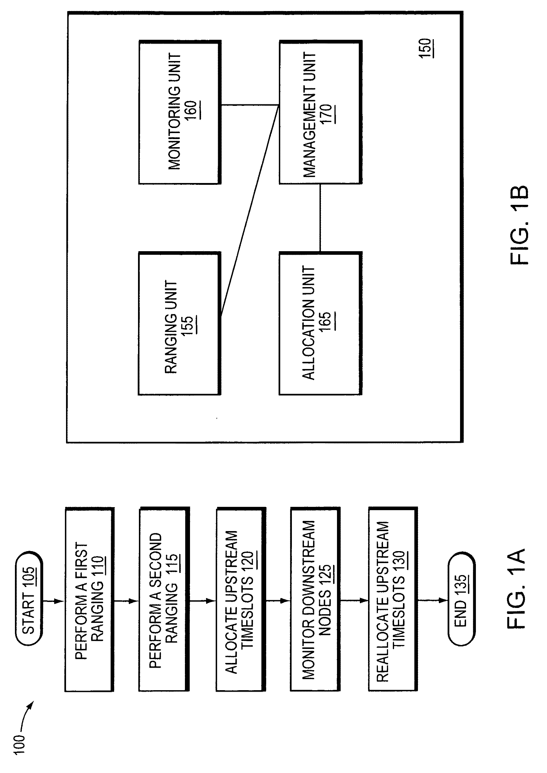
[0016]FIG. 1A is a flow diagram 100 illustrating an example embodiment method of the present invention for managing network nodes in a communications network. First, after the method commences (105), a first ranging (110) and a second ranging (115) are performed. Upstream timeslots are allocated (120) to downstream nodes based on timeslots assigned by an upstream node in the communications network. The downstream nodes are monitored (125) for a change of state, which may be a change of nodes or change of upstream communications. Based on results of at least one of the first ranging and the second ranging and a change of state of downstream nodes configured to communication in an upstream direction, upstream timeslots of the downstream nodes are reallocated (130). The method then ends (135).

[0017]FIG. 1B is a block diagram illustrating an example embodiment apparatus of the present invention for managing network node...


PUM


Abstract

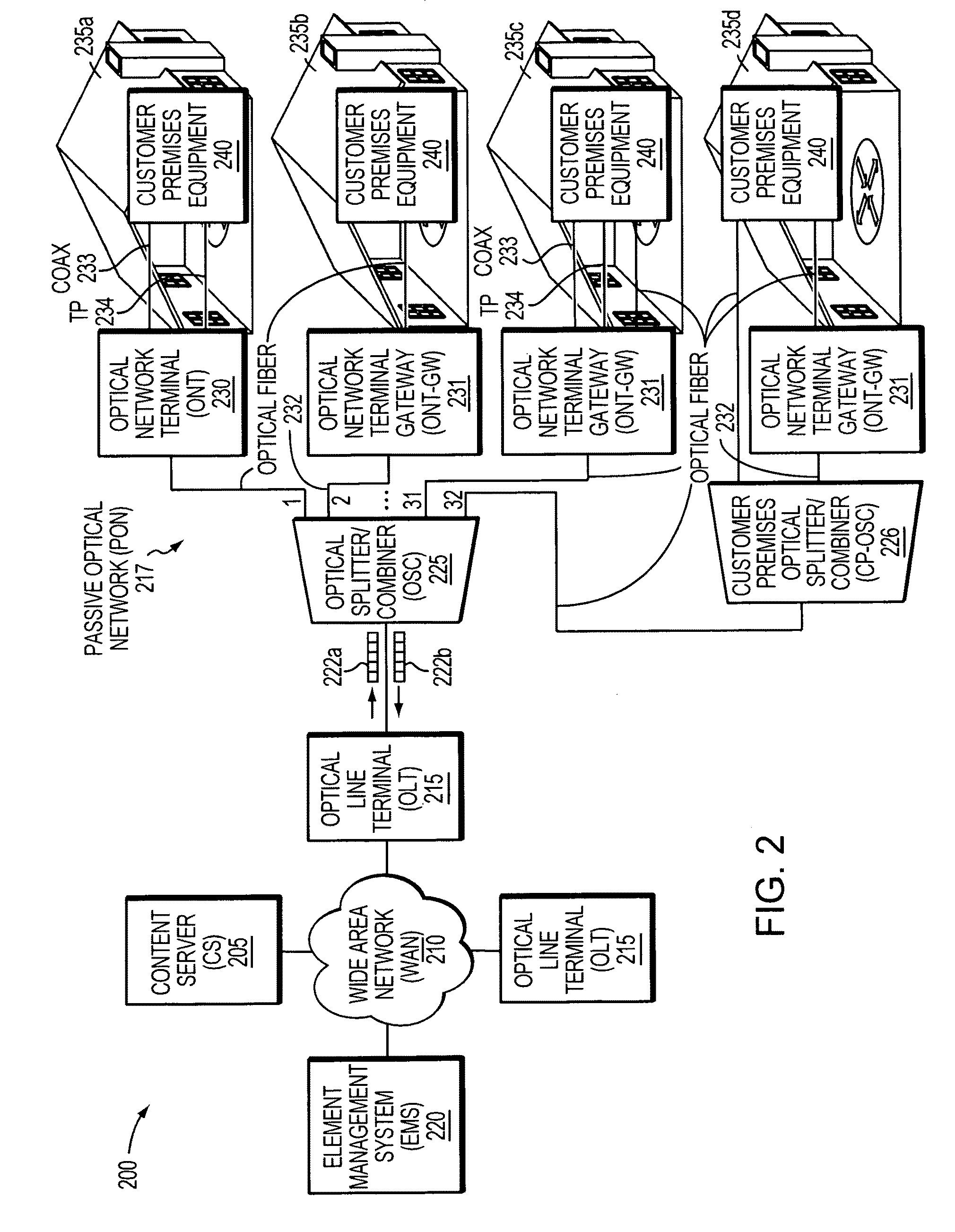
Example embodiments of the present invention help extend service provider visibility to all premises equipment (CPE) devices that are ranged with an Optical Line Terminal (OLT) by associating an Optical Network Terminal (ONT) within each device (CPE-ONT), such as a personal computer (PC), set-top box (STB), broadband home router (BHR), or analog telephone adapter (ATA). Therefore, each CPE device is managed independently via the CPE-ONT integrated with it. This allows each CPE device to terminate only optical signals supporting communications supported by the CPE device. Further, each CPE device has access to the entire GPON bandwidth, thereby increasing performance and eliminating bottlenecks caused by electrical communications over 10 / 100 / 1000 BaseT interfaces.

Description

BACKGROUND OF THE INVENTION[0001]There are traditional networking products that provide limited throughput due to hardware limitations. For example, in a Passive Optical Network (PON), specifically a Gigabit PON (GPON) or Broadband PON (BPON) frequently used in Fiber-to-the-Premises (FTTP) networks, some Optical Network Terminal (ONT) products provide one Gigabit Media Independent Interface (GMII) interface from an Optical Line Terminal (OLT) to an on-board Ethernet switch or network processor. However, this produces bandwidth constraints between the OLT and each Customer Premises Equipment (CPE) device connected to the ONT that is requesting bandwidth. Although multiple ONTs may be provided at a single customer premises, only 2.5 gigabits per second (Gbps) of bandwidth can be provided per wavelength to each device which cannot be shared across multiple devices. Moreover, traditional methods of providing bandwidth throughout a premises, such as over coaxial cable (COAX) using the Mu...

Claims


Application Information

Patent Timeline
Patent Type & Authority Applications(United States)
IPC IPC(8): H04L12/56
CPCH04L41/0893H04L43/0894H04L43/087H04L43/0852
Inventor BERNARD, MARC R.ATKINSON, DOUGLAS A.MERRITT, GUY M.LIU, DAVID H.KRALOWETZ, JOSEPH D.
Owner TELLABS VIENNA
Learn More