Direct detection receiver using cross-polarization interferometer for polmux-ask system

a cross-polarization interferometer and direct detection technology, applied in the field of optical communication systems, can solve the problems of generating cross-polarization beating noise between the two signals, unable to guarantee the alignment between the pbs and pbc, and not being able to detect the same wavelength in the same direction

Active Publication Date: 2009-12-17
NEC CORP
View PDF4 Cites 7 Cited by
  • Summary
  • Abstract
  • Description
  • Claims
  • Application Information

AI Technical Summary

Problems solved by technology

An obstacle to this process is the fact that polarization does not remain constant in optical fibers.
As a signal travels through the fiber, its polarization rotates Because of this effect, the alignment between the PBS and PBC is not guaranteed.
In addition, a crossing-polarization beating noise will be generated between the two signals.
However, the coherent detection receiver has drawbacks; both frequency offset and phase offset need to be removed by digital processing which requires large power consumption and complicated system design.
Coherent detection also requires a spare narrow line-width laser at the receiver as the local oscillator, which can increase both system cost and complexity.

Method used


Image

  • Direct detection receiver using cross-polarization interferometer for polmux-ask system
  • Direct detection receiver using cross-polarization interferometer for polmux-ask system
  • Direct detection receiver using cross-polarization interferometer for polmux-ask system

Examples


Embodiment Construction

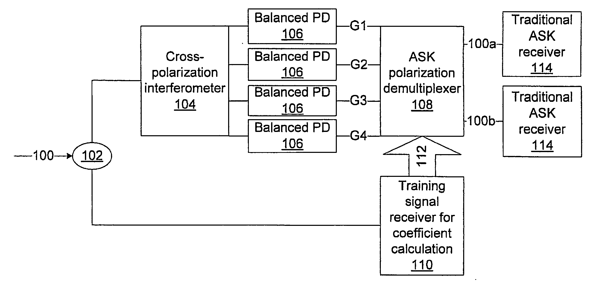
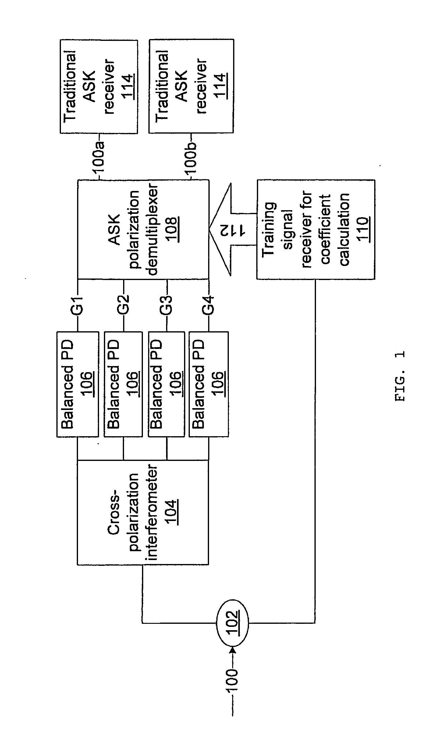
[0020]The present principles provide differential delay detection for polarization multiplexing (PolMux) systems, and in particular for PolMux-amplitude shift keying (ASK) systems. The differential delay detection can simplify a receiver design, improve system reliability and reduce cost by simplifying signal processing for a frequency offset and a phase offset and removing an expensive narrow line-width local oscillator laser.

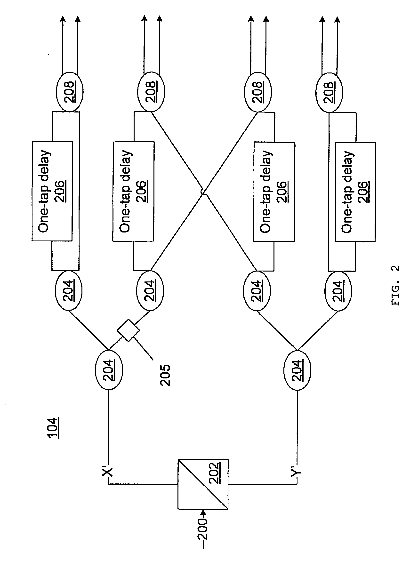
[0021]Through simulation, it has been proven that the cross-delay differential detection in accordance with the present principles can recover polarization rotation very well. As such, PolMux-ASK systems can benefit from using cross-delay differential detection instead of coherent detection, resulting in lower cost and complexity. In accordance with an illustrative embodiment, a 4-path butterfly cross-polarization differential delay (Mach-Zehnder) interferometer is employed to process the differential detection when signals are transmitted at two orthogonal po...


PUM


Abstract

A differential delay detection system and method includes an optical splitter to split an incoming optical signal between a first path and a second path. The first path includes a cross-polarization interferometer configured to separately generate polarization independent outputs using split paths and to generate cross-polarization interference outputs, balanced photodetectors to aid in removing cross-polarization beating noise, and a polarization demultiplexer configured to combine the polarization independent outputs and the cross-polarization interference outputs from the cross-polarization interferometer with updated coefficients received from the second path to remove the cross-polarization mixed signals. The second path includes a training signal receiver configured to compute the updated coefficients and output the updated coefficients to the polarization demultiplexer.

Description

RELATED APPLICATION INFORMATION[0001]This application claims priority to provisional application Ser. No. 61 / 060,702 filed on Jun. 11, 2008, incorporated herein by reference.BACKGROUND[0002]1. Technical Field[0003]The present invention relates to optical communications systems, and more particularly to an apparatus and a method for using cross-polarization interferometry in a direct-detection, polarization-multiplexing receiver.[0004]2. Description of the Related Art[0005]Coherent light may be transmitted in two orthogonal polarizations, where polarization refers to the orientations and relative phases of the electric and magnetic fields that make up the light. Light can be filtered through a polarizer, so that only those photons which have their electric fields along, for instance, a horizontal plane, may pass through. The result is that signals of two different polarizations (e.g., vertically polarized and horizontally polarized) may be transmitted along the same medium without in...

Claims


Application Information

Patent Timeline
Patent Type & Authority Applications(United States)
IPC IPC(8): H04J14/06
CPCH04B10/676H04L27/06H04J14/06
Inventor QIAN, DAYOUWANG, TING
Owner NEC CORP
Why Eureka
Try Eureka