Middle or Large-Sized Battery Module Employing Impact-Absorbing Member

Active Publication Date: 2009-12-17
LG ENERGY SOLUTION LTD
View PDF16 Cites 29 Cited by
  • Summary
  • Abstract
  • Description
  • Claims
  • Application Information

AI Technical Summary

Benefits of technology

[0038]Generally, a compact, light-weight battery module has a low mechanical safety. For example, the battery module may drop or collide with a solid body or structure due to external impacts. Also, internal short circuits may occur in the unit cells of the battery module when a needle-shaped conductor penetrates into the unit cells. Especially, when the external impacts are applied to the battery module in the direction in which the electrode plates of the unit cells are arranged, the safety of the battery module may be seriously deteriorated. Consequently, when the plate-shaped, high-strength safety member is mounted inside the upper case such that the safety member is arranged in parallel with the electrode plates of the unit cell, the battery module has a high mechanical safety although the weight of the battery module is slightly increased.
[0039]Preferably, the safety member is made of a high-strength metal material. More preferably, the safety member is made of stainless steel. Preferably, the safety member has a surface area corresponding to the unit cell and an appropriate thickness. When the thickness of the sa

Problems solved by technology

Furthermore, devices, which are subject to a large number of external impacts and vibrations, such as electric bicycles and electric vehicles, require stable electrical connection and physical coupling between components constituting the battery module.
The former example has an advantage in that the battery module has a structural stability but has a disadvantage in that the manufacturing costs of the battery module are high, and the size of the battery module is big.
However, the battery cell shown in FIG. 2 has a low mechanical strength although the battery module is constructed in any s

Method used


Image

  • Middle or Large-Sized Battery Module Employing Impact-Absorbing Member
  • Middle or Large-Sized Battery Module Employing Impact-Absorbing Member
  • Middle or Large-Sized Battery Module Employing Impact-Absorbing Member

Examples


example 1

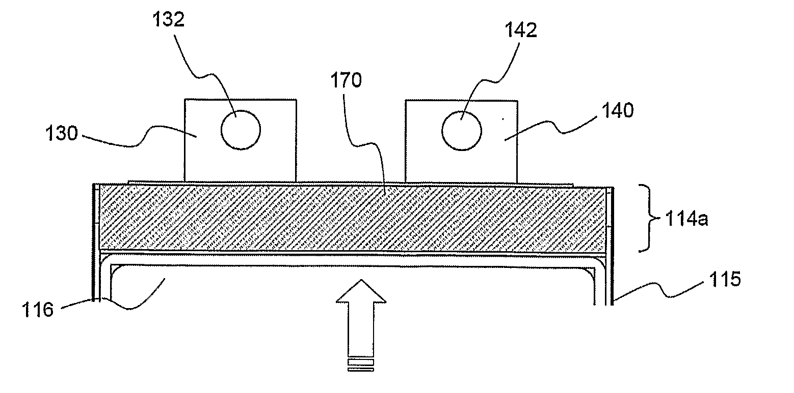
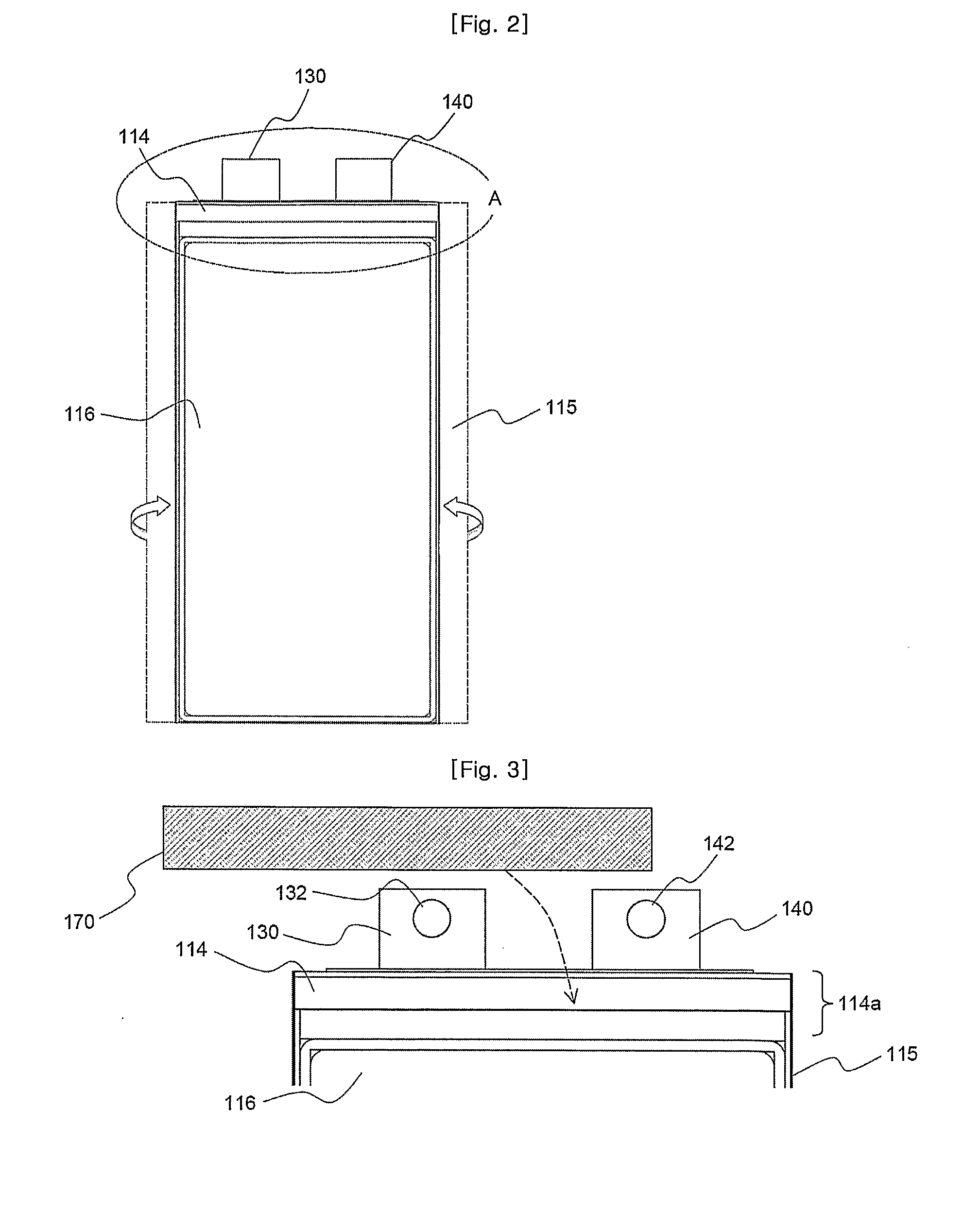
[0079]An electrode assembly was mounted in a battery case made of an aluminum laminate sheet, and the battery case was sealed by thermal heating to manufacture a battery cell having a width of approximately 94 mm, a length of approximately 185 mm (approximately 200 mm when including electrode taps), and a thickness of approximately 4.5 mm. The width of a thin upper end of the battery cell, including a sealing region, was approximately 12 mm. An impact-absorbing member having a size corresponding to the upper end of the battery cell and a thickness of approximately 4 mm and made of a porous rubber material was attached to the battery cell, as shown in FIGS. 3 and 4. A total of seven battery cells were manufactured such that the battery cells had the above-described construction, and the manufactured battery cells were stacked between an upper case and a lower case, as shown in FIGS. 5 and 6, to manufacture a battery module.

experimental example 1

[0081]The battery module manufactured according to Example 1 and the battery module manufactured according to Comparative example 1 were dropped with the upper ends of the respective battery cells down. The free dropping experiments were performed such that the battery modules were dropped from a height of 1 mm above the ground to a concrete floor so as to confirm the breakage or catching fire of the battery modules.

[0082]The results of the dropping experiments revealed that the upper ends of the battery cells broke and the electrode assemblies of the respective battery cells went out of the battery module after the 47-time dropping of the battery module manufactured according to Example 1. On the other hand, the upper ends of the battery cells broke and the electrode assemblies of the respective battery cells went out of the battery module after the 30-time dropping of the battery module manufactured according to Comparative example 1.

[0083]Consequently, it was confirmed that the b...

experimental example 2

[0084]Experiments ware performed to confirm the safety of the battery modules in conditions severer than Experimental Example 1.

[0085]Specifically, the battery module manufactured according to Example 1 and the battery module manufactured according to Comparative example 1 were dropped five times for each side with each side of the respective battery cells down, and then the battery module manufactured according to Example 1 and the battery module manufactured according to Comparative example 1 were repeatedly dropped with the upper ends of the respective battery cells down. The free dropping experiments were performed such that the battery modules were dropped from a height of 1 mm above the ground to a concrete floor so as to confirm the breakage or catching fire of the battery modules.

[0086]The results of the dropping experiments revealed that the battery module did not break and catch fire while the battery module manufactured according to Example 1 was dropped five times for ea...


PUM


Abstract

Disclosed herein is a battery module using battery cells each having an electrode assembly mounted in a battery case including a resin layer and a metal layer as unit cells, wherein each battery cell has a thin upper end, including a sealing part, which is formed at a region where electrode terminals are placed, and an impact-absorbing member is mounted at the upper end of each battery cell. The battery module according to the present invention prevents the weak upper parts of battery cells, such as electrode terminals and sealing parts, from the breakage of the battery module or the occurrence of a short circuit in the battery module due to the movement of the battery cells caused by dropping of the battery module or application of external impacts to the battery module. Furthermore, the battery module according to the present invention is constructed in a structure in which the battery module can be flexibly extended and contracted depending upon desired electrical capacity and output, wires used to electrically connect components constituting the battery module are compact, and the electrical connection between the components of the battery module is stably accomplished.

Description

FIELD OF THE INVENTION[0001]The present invention relates to a middle- or large-sized battery module including an impact-absorbing member, and, more particularly, to a battery module using battery cells each having an electrode assembly mounted in a battery case including a resin layer and a metal layer as unit cells, wherein each battery cell has a thin upper end, including a sealing part, which is formed at a region where electrode terminals are placed, and an impact-absorbing member is mounted at the upper end of each battery cell, thereby preventing the breakage of the battery case or the occurrence of a short circuit when an external force is applied to the electrode terminals and sealing parts of the respective unit cells.BACKGROUND OF THE INVENTION[0002]Recently, a secondary battery, which can be charged and discharged, has been widely used as an energy source for wireless mobile devices. Also, the secondary battery has attracted considerable attention as an energy source for...

Claims


Application Information

Patent Timeline
IPC IPC(8): H01M6/42H01M10/50H01M50/105H01M50/119H01M50/121H01M50/124H01M50/14H01M50/211H01M50/271H01M50/51H01M50/512H01M50/553H01M50/569
CPCH01M2/0237H01M2/0262H01M2/0287H01M2/10H01M2/1077Y02T10/7011H01M2/206H01M2/305H01M10/052H01M10/0585H01M2/202Y02E60/10H01M50/124Y02P70/50H01M50/105H01M50/121H01M50/512H01M50/51H01M50/569H01M50/211H01M50/271H01M50/14H01M50/553H01M50/119H01M50/20Y02T10/70
Inventor PARK, SEUNG YEOBYEO, JAE SEONGPARK, JONG HWANSHIN, YOUNGJOON
Owner LG ENERGY SOLUTION LTD
Why Eureka
Try Eureka