Method of double patterning using sacrificial structure

a technology of sacrificial structure and patterning method, which is applied in the direction of photomechanical treatment, photosensitive materials for photomechanical apparatuses, instruments, etc., can solve the problems of poor profile control, residual film left, poor profile control,

Inactive Publication Date: 2009-12-17
TOKYO ELECTRON LTD
View PDF6 Cites 37 Cited by
  • Summary
  • Abstract
  • Description
  • Claims
  • Application Information

AI Technical Summary

Problems solved by technology

However, current techniques for removing the light-sensitive layer may damage the BARC, leading to poor profile control and residual film left over before the spacer deposition.
In addition, if the BARC does not have the mechanical properties necessary to tolerate the stresses induced during the spacer formation process, then again, poor profile control may result.

Method used


Image

  • Method of double patterning using sacrificial structure
  • Method of double patterning using sacrificial structure
  • Method of double patterning using sacrificial structure

Examples


Embodiment Construction

[0018]In the following description, for the purposes of explanation and not limitation, specific details are set forth, such as particular processes and patterning systems. However, it should be understood that the invention may be practiced in other embodiments that depart from these specific details.

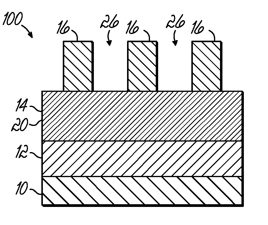
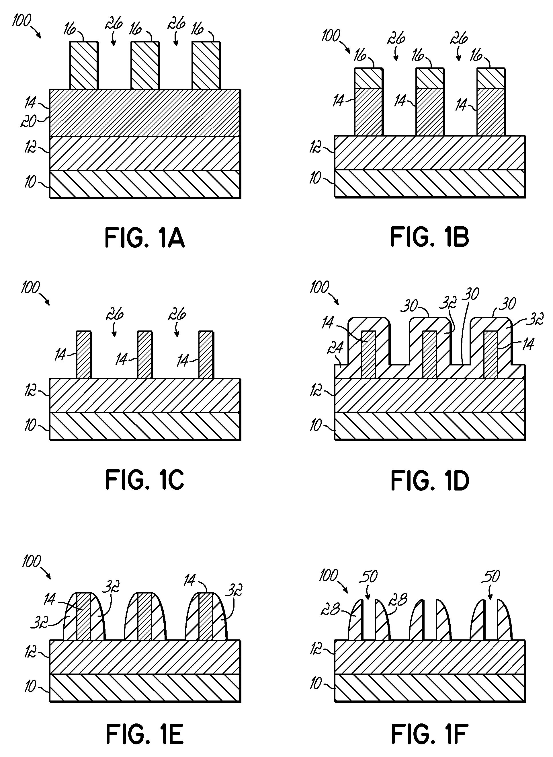
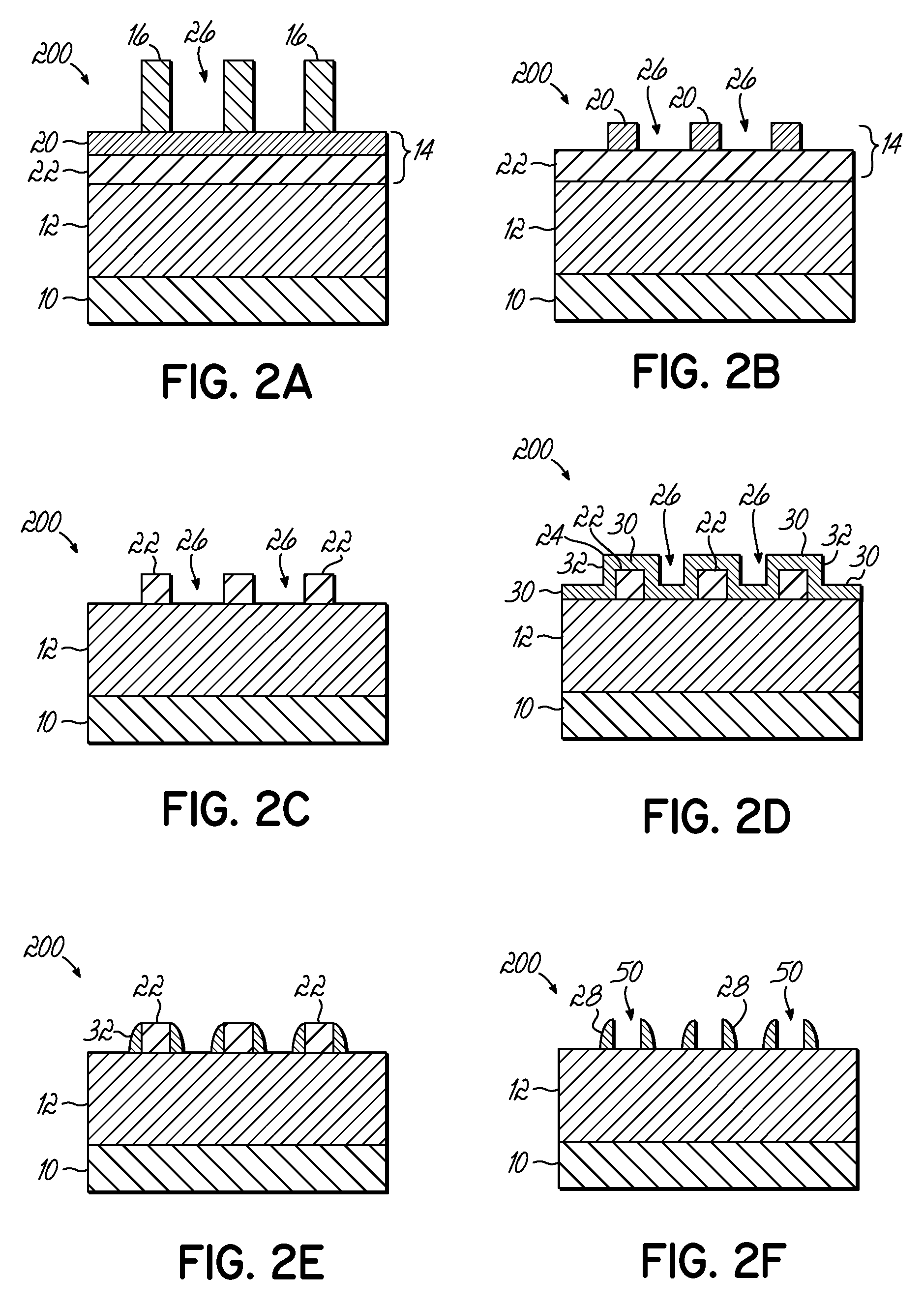
[0019]According to embodiments of the invention, illustrated in FIGS. 1A through 6B, methods of patterning a structure in a thin film 12 formed on a substrate 10 are schematically illustrated. The methods begin with forming a lithographic structure comprising a film stack 100, 200, 300, 400, and 500 formed on substrate 10. The film stack 100, 200, 300, 400, and 500 comprises a thin film 12 formed on substrate 10, a sacrificial structure 14 formed on the thin film 12, and a photo-resist layer 16 formed on the sacrificial structure 14. The sacrificial structure 14 may comprise an anti-reflective coating (ARC) layer 20 (e.g., a bottom ARC (BARC)) and may optionally include additional laye...


PUM

PropertyMeasurementUnit
dielectric constantaaaaaaaaaa

Abstract

A method of patterning a thin film on a substrate is described. The method includes forming a sacrificial structure over the thin film, and forming a photo-resist layer over the sacrificial structure. The sacrificial structure has anti-reflective properties, comprises silicon and is capable of withstanding the photo-resist layer removal process and the stress induced during the spacer layer deposition. Thereafter, an image pattern is formed in one or both of the sacrificial structure or the photo-resist layer. A spacer layer is then conformally deposited over the pattern. The spacer layer is etched back to remove horizontal portions while substantially leaving vertical portions. The remaining photo-resist and/or sacrificial structure that is not overlaid with the etched-back spacer layer is removed leaving spacers that are utilized to transfer another pattern to the thin film.

Description

BACKGROUND OF THE INVENTION[0001]1. Field of the Invention[0002]The present invention relates to a method of patterning a thin film on a substrate, and more particularly to a method of using a sacrificial structure and conformal deposition to pattern a thin film on a substrate.[0003]2. Description of the Related Art[0004]In material processing methodologies, pattern etching comprises the application of a thin layer of light-sensitive material, such as photo-resist, to an upper surface of a substrate that is subsequently patterned in order to provide a mask for transferring this pattern to the underlying thin film on a substrate during etching. The patterning of the light-sensitive material generally involves exposure by a radiation source through a reticle (and associated optics) of the light-sensitive material using, for example, a photo-lithography system, followed by the removal of the irradiated regions of the light-sensitive material (as in the case of positive photo-resist), o...

Claims


Application Information

Patent Timeline
Patent Type & Authority Applications(United States)
IPC IPC(8): G03F7/004
CPCH01L21/0338H01L21/0337
Inventor YUE, HONGYULAM, HIEU A.NIINO, REIJI
Owner TOKYO ELECTRON LTD
Why Eureka
Try Eureka