Entrainment air flow control and filtration devices

a technology of air flow control and filtration device, which is applied in the direction of energy-efficient board measures, domestic heating details, and weight reduction, etc., can solve the problems of insufficient air circulation through central heating, ventilation and air-conditioning systems to dilute air contaminants to safe levels, and insufficiently address direct person-to-person air contaminant and pathogen spread. , to achieve the effect of reducing

Active Publication Date: 2009-12-17
VEFT AEROSPACE TECH
View PDF16 Cites 57 Cited by
  • Summary
  • Abstract
  • Description
  • Claims
  • Application Information

AI Technical Summary

Benefits of technology

[0012]It is an object of the present invention to provide improved devices, components and systems for use with heating, ventilating and air-conditioning systems, air curtain systems, and air circulation systems. It is a further object to provide such devices, components and systems which may provide one or more of improved device performance, energy savings, elimination of recirculation systems, and local air cleaning, purification and / or filtering, without using local fans or compressors.
[0018]The combined entrained or secondary air and the primary air supply from ventilation ducting, from an air supply control device such as a VAV box, or from a diffuser air supply, are combined in a mixing chamber and then discharged back into the ventilation system ducting or to the space being served by the diffuser. The discharge velocity can be tailored as wished to be, for example, at a sufficiently low velocity when the outlet air is being diffused into a space to reduce subsequent entrainment in the space. In various aspects the invention may increase air circulation to occupants and treat air contaminants in the ambient air it entrains and if desired also in the primary airflow. In another aspect the mixing of the entrained ambient air with the primary air flow in the mixing chamber may reduce the thermal and humidity gradients that otherwise exist between the air exiting an air outlet and the air in the space being served. It can entrain warm or cool air locally which will thermally condition the air being supplied to the space. The device can be designed to control the combined air flow so as supply a relatively constant volume of air even when the primary air supply modulates higher or lower.
[0019]The invention lends itself to the use of relatively large media filter areas. This is advantageous as the larger the air filter surface area for the space or number of persons being served, the lower the pressure loss across the filter, the longer the air passage time in the filter or purifier, the higher the filter efficiency in removing air contaminants and the higher the filtered entrainment ventilation flows to the area and occupants being served. The ambient air entrainment section (a pipe or plenum) provides the fluid connection to the mixing pipe or chamber (mix chamber). The high velocity injection airflow enters the mix chamber through a nozzle with one or more jet or orifice outlets. This nozzle preferably directs air towards the mix chamber and not toward the entrainment pipe or plenum. The momentum of the high velocity airflow draws ambient air into the mix chamber via the connected entrainment section.
[0022]According to one aspect, the invention relates to a device for use with a high speed primary air flow comprising a mixing chamber having an entrance, a nozzle directed towards the mixing chamber entrance, an entrainment chamber, a connection between the entrainment chamber and the mixing chamber, and an air outlet from the mixing chamber to the ventilation system ducting, a diffuser or other air control device. The entrainment chamber preferably contains a filter subcompartment with a filter, air purifier, and / or a gaseous sorber / converter. According to another aspect, the nozzle comprises an array of at least four jets, and said mixing chamber has a length to inside diameter ratio that approximates unity as a minimum. It has been found that the use of a nozzle comprising four or more jets permits use of a mixing chamber having this minimum length to diameter ratio, which in turn permits a relatively short length structure. By way of example, a mixing tube may have a length and inside diameter of about two inches to permit a relatively compact mixing chamber.
[0023]According to another aspect, the mixing chamber comprises two or more side walls which diverge towards the air outlet. The walls may diverge by one or more of the walls being sloped by between 0 and 25 degrees from the vertical when the chamber is in a vertical orientation. It has been found that this configuration tends to enhance entrainment and can be helpful in increasing occupant comfort by reducing the velocity of air exiting the mixing chamber.

Problems solved by technology

Moving sufficient air through central heating, ventilation and air-conditioning (HVAC) systems to dilute these air contaminants to safe levels can be costly, as can the extensive use of portable air cleaners.
Air contaminants such as chemicals and pathogenic organisms, and ventilation air supply thermal and humidity gradients, particularly in high occupancy enclosed spaces such as in transportation vehicles, can present health and comfort concerns due to the limitations of existing ventilation systems using conventional air flow controllers and outlet diffusers to deliver air cleaned centrally.
Existing systems may filter, purify and / or clean the air delivered and thus provide a limited amount of local dilution of air contaminants but they have limitations: pathogens and air contaminants, for example, can still be circulated locally by the airflow patterns introduced by the diffusers, by occupant movement and other forces, travelling laterally between occupants before being returned to a central air cleaner and conditioner system.
Ventilation air and air curtain air boundary layers can entrain contaminants (including dust and insects), causing them to enter the occupant breathing zone or space being protected.
One problem lies in part in the entrainment into the ventilation air of localized air pathogens, dust, odours, insects as it passes on its way from the diffusers to the occupant breathing zones.
Ventilation systems do not adequately address direct person-to-person air contaminant and pathogen spread.
Prior flow controller and diffuser designs do not filter out air contaminants in the local space, which is where many air contaminants are generated.

Method used


Image

  • Entrainment air flow control and filtration devices
  • Entrainment air flow control and filtration devices
  • Entrainment air flow control and filtration devices

Examples


Embodiment Construction

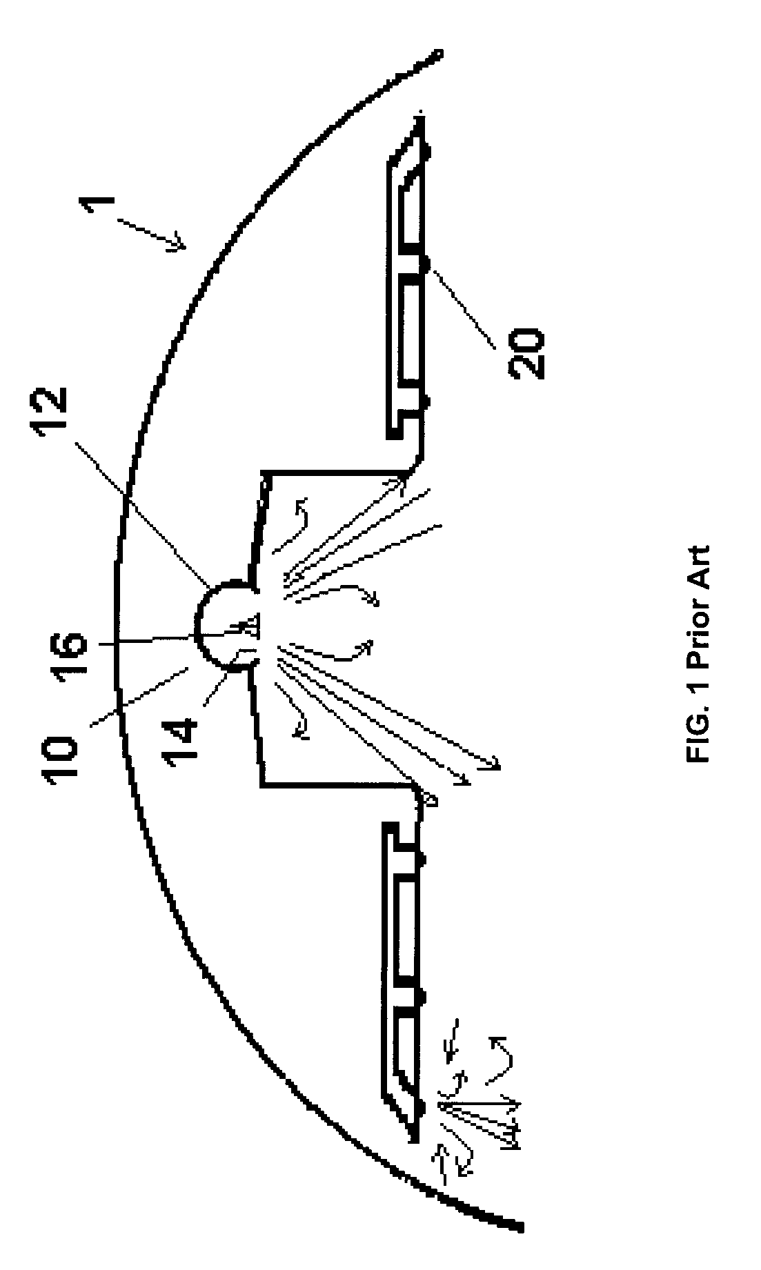
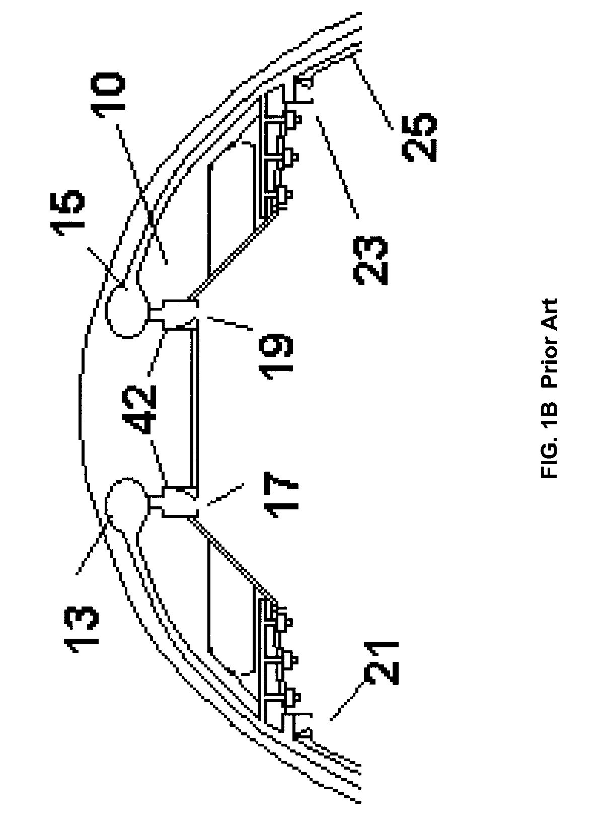
[0111]In a first embodiment, a diffuser for a ventilation system is provided which is particularly suited for aircraft and other similar enclosed cabins such as trains and buses. Although referred to generally herein as an aircraft or aircraft-type diffuser, persons skilled in the art will understand that numerous applications of this system are possible with suitable modifications. FIGS. 1, 2, 3 and 5 illustrate various prior art systems installed within a generally conventional passenger aircraft fuselage 1. FIG. 1 is a cross-sectional schematic view of a prior art aircraft ventilation system 10 comprising a central duct 12 running substantially the length of the cabin, having a two slots 14 for diffusing airflow into the cabin interior. Typically, the slots direct air generally laterally along the ceiling, with the two slots being oriented in opposing directions. Directional vanes 16 may be provided, which direct the airflow in a desired direction or if vanes slanted in opposing ...


PUM

PropertyMeasurementUnit
diameteraaaaaaaaaa
flow rateaaaaaaaaaa
velocityaaaaaaaaaa

Abstract

Devices and systems are provided, that entrain ambient air within a primary stream of pressurised air, for use in a variety of applications including aircraft, buildings and other stationary structures. The ambient air is drawn through an air treatment such a filter before entrainment within the primary stream. The combined streams are then delivered to a ventilation system, an air curtain or other suitable recipient of treated, thermally conditioned air. The systems include air curtain systems and ventilation systems for aircraft and other vehicles.

Description

[0001]This application claims the Convention Priority benefit of U.S. Patent application No. 60 / 805,672 filed on Jun. 23, 2006, which is incorporated in its entirety herein by reference.FIELD OF THE INVENTION[0002]The present invention relates to air ventilation, filtration, purification, cleaning, thermal, humidity and pressure conditioning. It relates more particularly to apparatus for attachment to or use with an air supply system, such as an airplane, automobile or building ventilation system, or an air curtain system.BACKGROUND OF THE INVENTION[0003]Spaces where occupancy density and consequently the potential for human pathogen spread is high, or where processes create air pollutants such as dust, gases are prime candidates for local ventilation entrainment and recirculation, filtration, air purification and air cleaning. Such spaces where occupant generated pathogens and irritants are a concern include aircraft passenger cabins, conference rooms, trains, trains, buses, subway...

Claims


Application Information

Patent Timeline
Patent Type & Authority Applications(United States)
IPC IPC(8): F24F13/04A61L9/00B01D50/00B60H1/26B60H3/00F24F13/10
CPCB60H3/0007B60H3/0014B64D13/00B64D2013/0625F24F5/0085F24F13/26Y02T50/44Y02T50/56B64D2013/0651Y02T50/40Y02T50/50
Inventor WALKINSHAW, DOUGLAS STUART
Owner VEFT AEROSPACE TECH
Why Eureka
Try Eureka