Device and method for detecting in-vivo pathology

a pathology and in-vivo technology, applied in the field of in-vivo pathology detection, can solve the problems of difficult to detect specific bindings within an in-vivo environment, difficult to sense optical changes of the same kind,

Active Publication Date: 2009-12-17
GIVEN IMAGING LTD
View PDF102 Cites 23 Cited by
  • Summary
  • Abstract
  • Description
  • Claims
  • Application Information

AI Technical Summary

Benefits of technology

[0010]Embodiments of the present invention provide a device and method for detecting in-vivo markers. Embodiments of the present invention provide a device which allows for free flow of in-vivo fluids through the device body.

Problems solved by technology

However, it may be difficult to sense an optical change of the same sort as described above when the quantity or concentration of an in-vivo marker is not high.
It may also be difficult to detect specific bindings within an in-vivo environment, due to high background noise in this environment, i.e., reflected illumination other than the optical change to be detected.

Method used


Image

  • Device and method for detecting in-vivo pathology
  • Device and method for detecting in-vivo pathology
  • Device and method for detecting in-vivo pathology

Examples


Embodiment Construction

[0047]In the following detailed description, numerous specific details are set forth in order to provide a thorough understanding of the invention. However, it will be understood by those skilled in the art that the present invention may be practiced without these specific details. In other instances, well-known methods, procedures, and components have not been described in detail so as to not obscure the present invention.

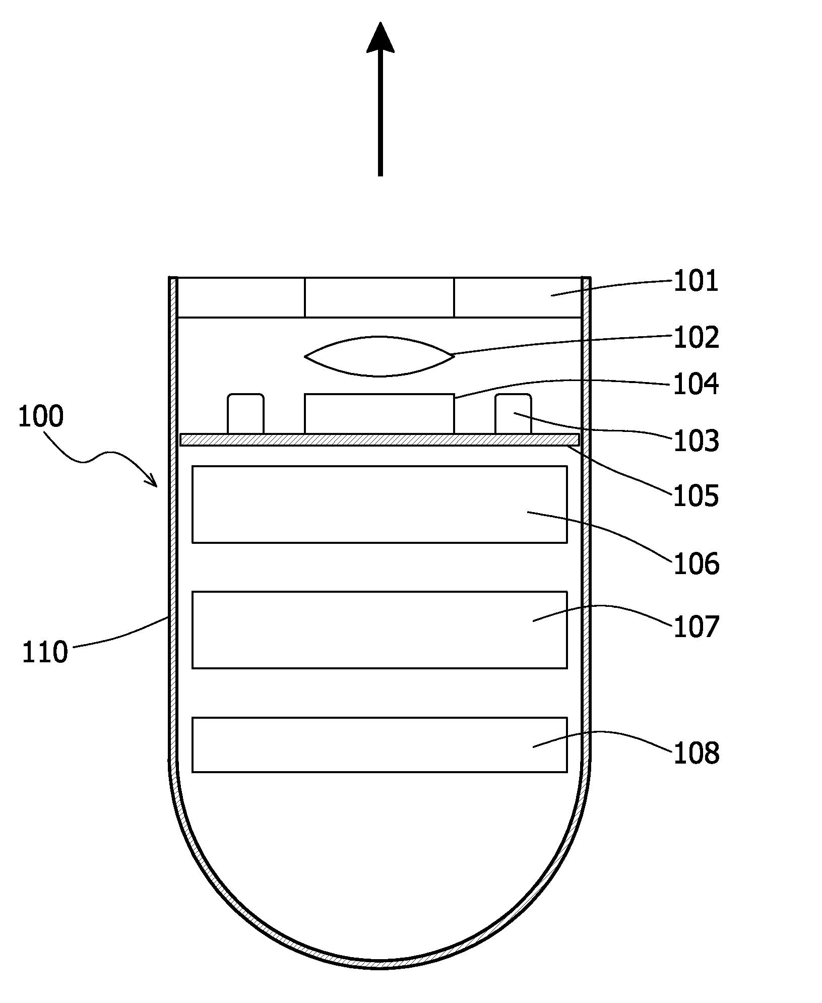
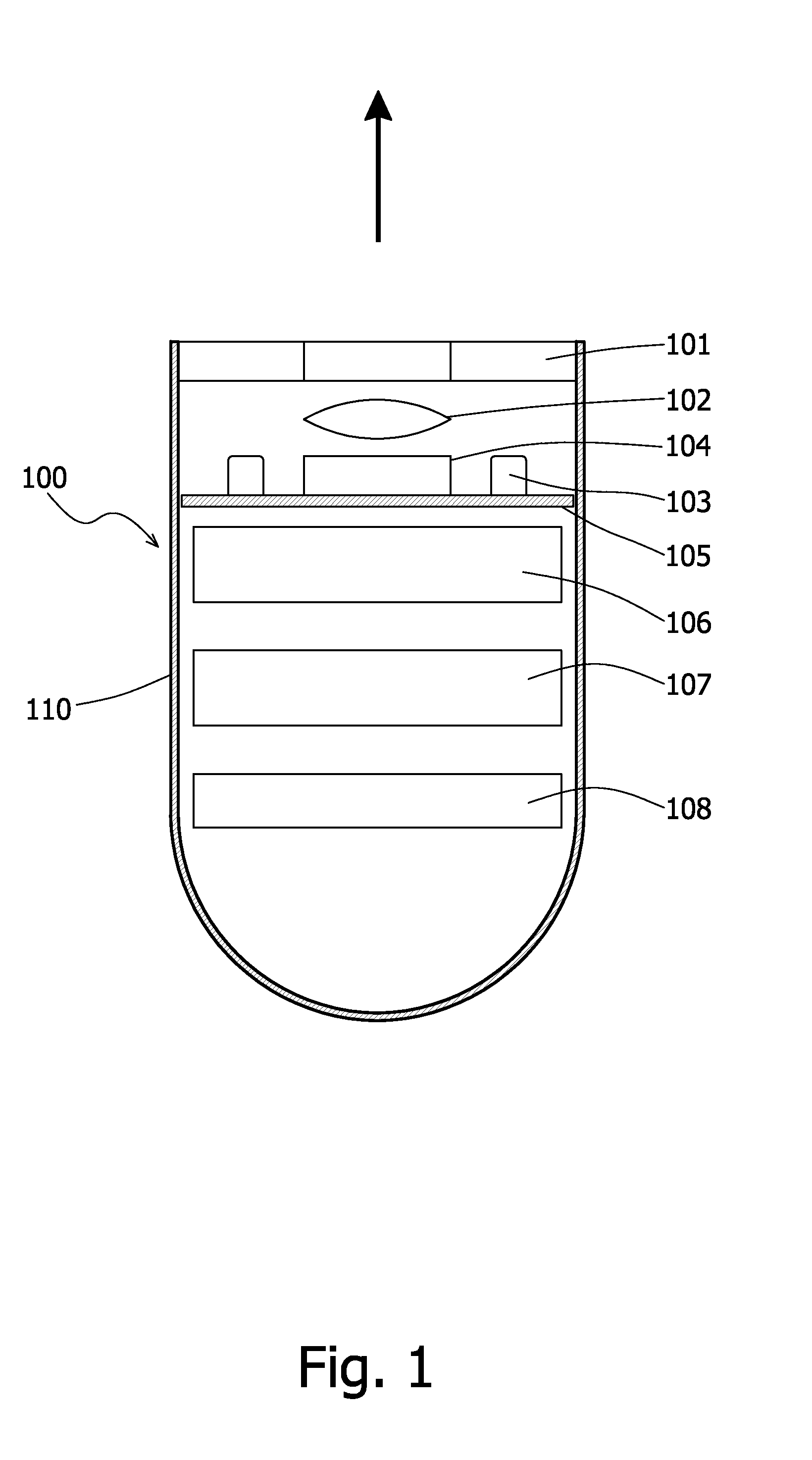
[0048]Reference is now made to FIG. 1, which provides a schematic illustration of an in-vivo sensing device in accordance with one embodiment of the invention. According to one embodiment, the in vivo sensing device is a swallowable imaging capsule. According to an embodiment of the invention, as described in FIG. 1, there is provided an in-vivo sensing device 100, comprising a reacting layer 101, which is positioned at the end of the device body 110. Reacting layer 101 may be perpendicular to a forward sensing direction of device 100. However, in other embodiment...


PUM


Abstract

Devices, systems and methods for detecting in vivo pathology are provided. An in vivo sensing device comprises a reacting layer with at least one type of binding agent attached thereon, a sensor configured for sensing an optical change occurring on the reacting substrate, and at least one illumination source. In-vivo fluids are in constant contact with the reacting substrate so that in vivo marker indicating pathology may bind to the binding agent attached onto the reacting layer and may be viewed by the sensor.

Description

FIELD OF THE INVENTION[0001]The present invention relates to the field of detecting in-vivo pathology. More specifically the present invention relates to a device and method for detecting in-vivo markers indicating pathology.BACKGROUND OF THE INVENTION[0002]The mammalian and human bodies enclose specific biological markers in-vivo, which may indicate various pathologies in the living body. Early detection of such markers could mean early detection of pathologies in the body, which would lead to better treatment. Each specific in-vivo marker can bind to a specific biological particle such as an antibody, peptide and other binding agents.[0003]These markers may be detected by sensing an optical change which occurs due to binding of a binding agent to a marker in-vivo, for example, detecting fluorescence at a given bandwidth, emitted from a binding agent bound to a marker in-vivo.[0004]An additional method of detecting binding between molecules is “Fluorescence resonance energy transfe...

Claims


Application Information

Patent Timeline
Patent Type & Authority Applications(United States)
IPC IPC(8): A61B6/00
CPCA61B1/041A61B5/0084A61B5/0071A61B1/043
Inventor RABINOVITZ, ELISHASELLA-TAVOR, OSNATPASCAL, AMITEMANUEL, NOAM
Owner GIVEN IMAGING LTD
Why Eureka
Try Eureka