Pintle-controlled propulsion system with external dynamic seal

a dynamic seal and propulsion system technology, applied in the field of nozzles, can solve the problems of increasing thrust, increasing the pressure upstream of the throat, and limited variation produced by such a design, and achieves the effect of small thrust chambers and greater thermal stando

Inactive Publication Date: 2009-03-31
AEROJET GENERAL CORP
View PDF13 Cites 10 Cited by
  • Summary
  • Abstract
  • Description
  • Claims
  • Application Information

AI Technical Summary

Benefits of technology

[0007]The present invention resides in a novel arrangement of pintle, pintle actuator and dynamic seal that places the seal at a distance from the thrust chamber. This offers advantages that include a smaller thrust chamber size and greater thermal stand-off, which is the ability to maintain the seal at a lower temperature than the chamber, either due to heat dissipation along the length of the pintle or to a sufficient distance between the seal and the site of highest temperature in the chamber. The arrangement also provides the thruster with a longer duty cycle. These advantages are achieved by constructing the pintle with a shaft that extends through the thrust chamber wall and constructing the chamber with a boss on the external surface of the chamber wall, with a dynamic seal inside the boss and arranged to engage the pintle shaft. Actuation of the pintle is achieved by a rack affixed to the pintle shaft and a gear engaging the rack, both rack and gear being external to the chamber as well. In preferred embodiments of the design, the rack and gear are both external to, but in close proximity to, the boss.
[0008]With both the dynamic seal and the actuator external to the thrust chamber, the invention allows the thrust chamber to be of relatively reduced size. This provides the chamber with a more compact external envelope without reducing the thermal standoff, and allows the chamber to be light in weight and to occupy only a small volume in the rocket motor. The invention also allows the thrust chamber to be constructed with increased thermal standoff without an increase in length. The increased thermal standoff allows the thruster to withstand a longer exposure time to hot combustion gases, and thereby a longer duty cycle. This leads to improved performance of the thruster and allows the thruster to be used for a greater number of mission operations.

Problems solved by technology

The variability produced by such a design was limited however and not controllable during flight, and the shape of the propellant grain was often optimal for only one of the phases, usually the boost phase.
A decrease in the effective throat area raises the pressure upstream of the throat and thereby increases the thrust.
One of the challenges that are faced in the design of a pintle-actuated thrust chamber is the need to control the wear on and damage to the pintle actuator that are caused by the exposure of the actuator to the harsh conditions of the thrust chamber, notably the high temperatures and pressures in the chamber.
The wear that these conditions produce on the actuator components causes the actuator to deteriorate and thereby limit the duty cycle of the thruster.
Another challenge is the need for a dynamic seal between the pintle and the thrust chamber that will both retain the pressure and accommodate the movement of the pintle.
In these designs as well, the chamber must be large enough to enclose the actuator and therefore consumes valuable space within the propulsion system.
Even in the wall, however, the seal is still exposed to the high temperature of the thrust chamber and the resulting deterioration limits the useful life span of the seal.

Method used


Image

  • Pintle-controlled propulsion system with external dynamic seal
  • Pintle-controlled propulsion system with external dynamic seal
  • Pintle-controlled propulsion system with external dynamic seal

Examples


Embodiment Construction

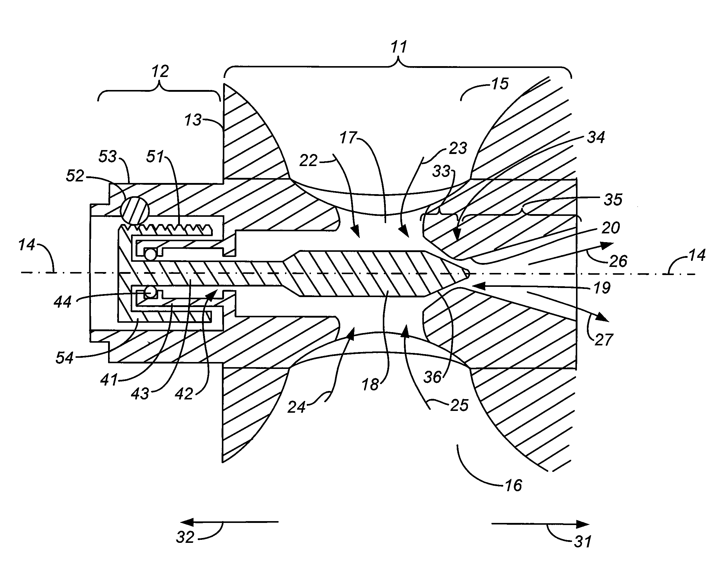
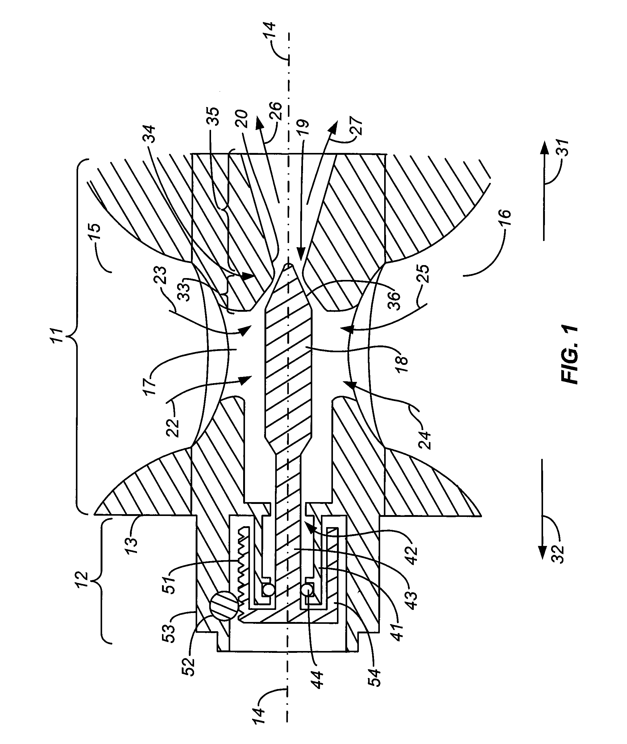
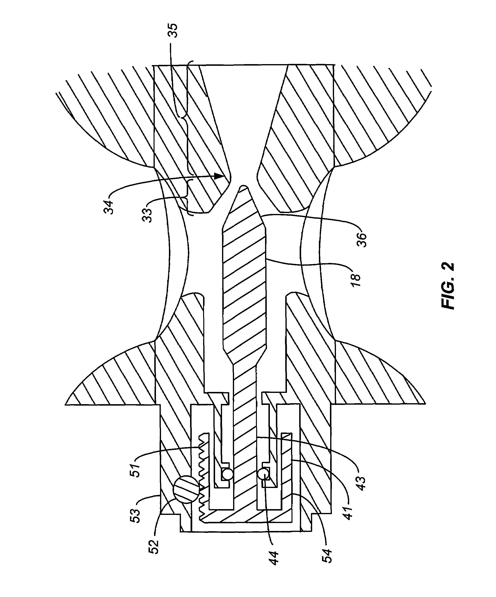
[0014]While the invention is susceptible to a number of implementations and embodiments in terms of the design and construction of the propulsion system, an understanding of the full scope of invention can be gained by a detailed review of a single embodiment. One such embodiment is depicted in the drawings hereto and explained below.

[0015]The system shown in FIGS. 1 and 2 includes a thrust chamber 11 and a seal and actuator section 12 that is mounted to the outer surface 13 of an external wall of the thrust chamber. The thrust chamber in this embodiment is a body of revolution about an axis 14. Combustion gases enter the thrust chamber 11 through lateral inlets 15, 16, the gases being either fully combusted upon entry or partially combusted to complete combustion within the thrust chamber cavity 17. Although two such inlets 15, 16 are shown, a single inlet may be sufficient in certain constructions, but preferred constructions are those that include a plurality of such inlets symme...


PUM


Abstract

A propulsion system with a pintle for variable thrust is constructed such that the pintle contains a shaft at its fore end which passes through an opening in the thrust chamber wall and extends into a boss on the outside surface of the thrust chamber. A dynamic seal that maintains the pressurization of the thrust chamber while allowing movement of the pintle is positioned inside the boss, between the pintle shaft and the boss, and actuation of the pintle is achieved by a rack affixed to the fore end of the pintle and a gear that engages the rack. The dynamic seal, rack and gear are thus external to the thrust chamber, providing the thrust chamber with a compact external envelope, a greater thermal standoff, or both.

Description

BACKGROUND OF THE INVENTION[0001]1. Field of the Invention[0002]This invention resides in the field of propulsion systems with variable thrust, and in particular to nozzles that utilize pintles to vary the nozzle throat area.[0003]2. Description of the Prior Art[0004]Mechanisms for thrust variation have long been used to provide rocket motors with a relatively high thrust at the boost stage and a low thrust during the sustain phase. Early efforts to achieve this type of boost-sustain transition focused on the configuration of the solid propellant grain to provide a high burning surface area in the early stages of burning while the shape of the propellant grain by itself caused a reduction in the burning surface area as burning progressed. The variability produced by such a design was limited however and not controllable during flight, and the shape of the propellant grain was often optimal for only one of the phases, usually the boost phase. Subsequent efforts focused on the throat ...

Claims


Application Information

Patent Timeline
Patent Type & Authority Patents(United States)
IPC IPC(8): F02K1/08
CPCF02K9/26F02K9/30F02K9/32F02K9/86G05D7/0635
Inventor HANSEN, WILLIAM E.
Owner AEROJET GENERAL CORP
Why Eureka
Try Eureka