Method to design network-on-chip (NOC) - based communication systems

a communication system and network-on-chip technology, applied in the field of network-on-chip (noc)based communication systems, can solve the problems of high design complexity of mcss, increased computation and communication complexity of design, and complex process for designing an efficient noc architecture while satisfying application performance constraints

Active Publication Date: 2009-12-17
ECOLE POLYTECHNIQUE FEDERALE DE LAUSANNE (EPFL)
View PDF6 Cites 117 Cited by
  • Summary
  • Abstract
  • Description
  • Claims
  • Application Information

AI Technical Summary

Problems solved by technology

MCSs have high design complexity and are widely used in several application domains such as wireless platforms, multi-media devices and telecommunication platforms, to name a few.
This results in increased computation and communication complexity of the design, and scalable approaches are needed to design the system.
Designing an efficient NoC architecture while satisfying the application performance constraints is a complex process.

Method used


Image

  • Method to design network-on-chip (NOC) - based communication systems
  • Method to design network-on-chip (NOC) - based communication systems
  • Method to design network-on-chip (NOC) - based communication systems

Examples


example 1

[0054]The min-cut partitions of the core graph of the filter example (from FIG. 4) for 3 partitions is shown in FIG. 6(a). The SCG for the 3 partitions is shown in FIG. 6(b). After applying the turn prohibition algorithm, the set of prohibited turns is identified. In FIG. 6(b), the prohibited turns are indicated by circular arcs in the SCG. For this example, both the turns around the vertex P3 are prohibited to break cycles. So no path that uses the switch P3 as an intermediate hop can be used for routing packets.

[0055]The actual physical connections between the switches are established in step 8 of Algorithm 2 using the PATH_COMPUTE procedure. The objective of the procedure is to establish physical links between the switches and to find paths for the traffic flows across the switches. Here, we only present the procedure where the user's design objective is to minimize power consumption. The procedures for the other two cases (with hop count as the objective and with linear combinat...

example 2

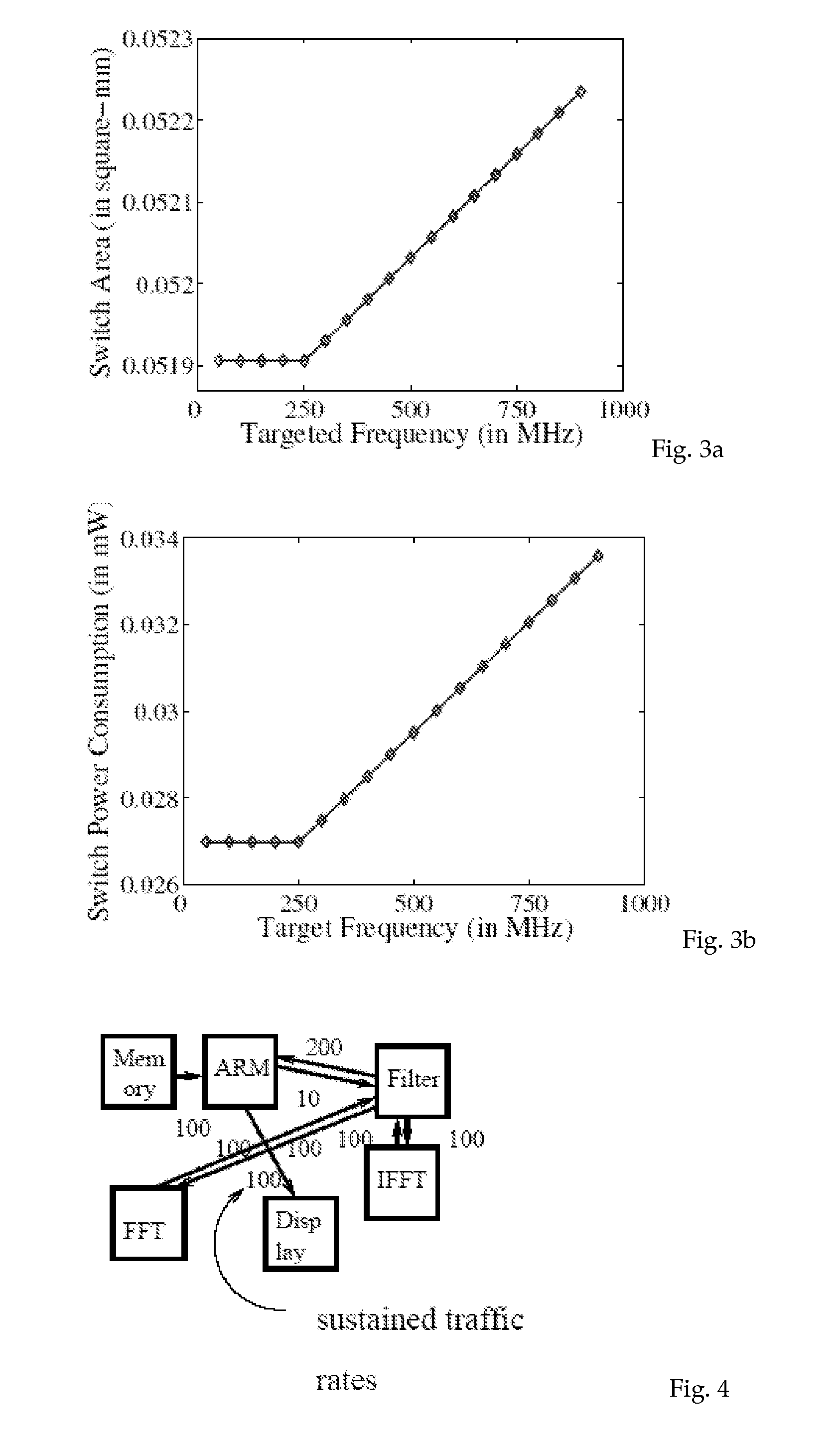
[0059]Let us consider the example from FIG. 6(a). The input core graph has been partitioned into 4 partitions. We assume 2 different message types: request and response for the various traffic flows. Each partition pi corresponds to the cores attached to the same switch. Let us consider routing the flow with a bandwidth value of 100 MB / s between the vertices v1 and v2, across the partitions p1 and p2. The traffic flow is of the message type request. Initially no physical paths have been established across any of the switches. If we have to route the flow across a link between any two switches, we have to first establish the link. The cost of routing the flow across any pair of switches is obtained. We annotate the edges between the switches by the cost (marginal increase in power consumption) of sending the traffic flow through the switches (FIG. 6(c)). The costs on the edges from p2 are different from the others due to the difference in initial traffic rates within p2 when compared...


PUM


Abstract

A method to design a Networks on Chips (NoCs)-based communication system for connecting on-chip components in a multicore system, said system comprising several elements communicating through the communication system, said communication system comprising at least switches, said method comprising the steps of modelling the applications running on the multicore system, establishing the number and configuration of switches to connect the elements, establishing physical connectivity between the elements and the switches, for each two pairs of communicating elements: (a) a defining a communication path, (b) calculating metrics as affected by the need to render said path into physical connectivity, taking into account any previously defined physical connectivity, (c) iterating the steps a and b for a plurality of possible paths, (d) choosing the path having the optimal metrics, and (e) establishing any missing physical connectivity between the switches so that the selected optimal path occurs across physically connected switches.

Description

1 INTRODUCTION[0001]Today's multicore systems (MCSs) integrate several processor cores, hardware blocks, co-processors, memories, Digital Signal Processors (DSPs) and I / O blocks on the same chip. MCSs have high design complexity and are widely used in several application domains such as wireless platforms, multi-media devices and telecommunication platforms, to name a few.[0002]Due to technology scaling, the number of processor, memory and hardware cores integrated on an MCS are increasing. This results in increased computation and communication complexity of the design, and scalable approaches are needed to design the system. As wire scaling is not on-par with transistor scaling, the interconnect architecture is becoming a bottleneck for the entire system performance and efficient ways to tackle the communication architecture complexity is needed.[0003]Traditionally, bus-based architectures have been used to interconnect the various cores of the MCSs. To meet the increasing communi...

Claims


Application Information

Patent Timeline
Patent Type & Authority Applications(United States)
IPC IPC(8): G06F17/50
CPCG06F17/5045H04L49/25G06F2217/08G06F30/30G06F2111/06
Inventor MURALI, SRINIVASANBENINI, LUCADE MICHELI, GIOVANNI
Owner ECOLE POLYTECHNIQUE FEDERALE DE LAUSANNE (EPFL)
Why Eureka
Try Eureka