
Modular building system

a modular building and building technology, applied in the field of modular buildings, can solve the problems of limited prefabrication systems of wood and aluminum frames, general labor and cost intensive building construction field, and limited prefabrication time for building construction, so as to achieve convenient erection and disassembly and transport.

Inactive Publication Date: 2009-12-24
SHELTER TECH
View PDF7 Cites 24 Cited by
  • Summary
  • Abstract
  • Description
  • Claims
  • Application Information

AI Technical Summary

Benefits of technology

[0009]In view of the foregoing disadvantages inherent in the prior art, the general purpose of the present invention is to provide prefabricated building structures such as a modular building system for configuring a building structure that is configured to include all advantages of the prior art, and to overcome the drawbacks inherent therein.
[0011]Another object of the present invention is to provide a modular building system that may be easily erected and dismantled, and may be customizable to meet changing requirements in size and needs of long-term or permanent applications of buildings, or places of the buildings.
[0012]Yet another object of the present invention is to provide a modular building system that may be able to withstand poor weather conditions and may provide insulation from noise, heat and cold.
[0013]Still another object of the present invention is to provide a modular building system that may be readily transportable.
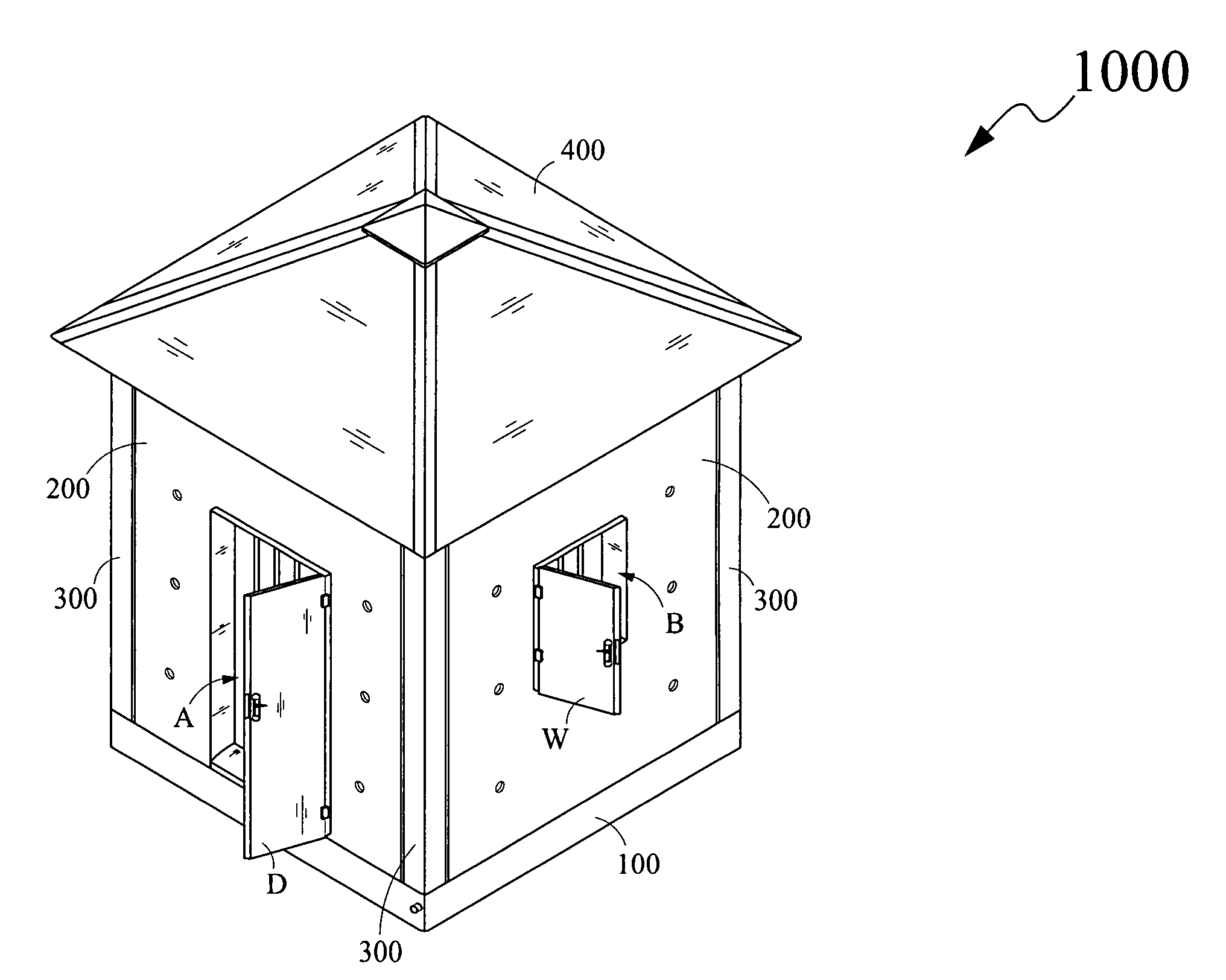
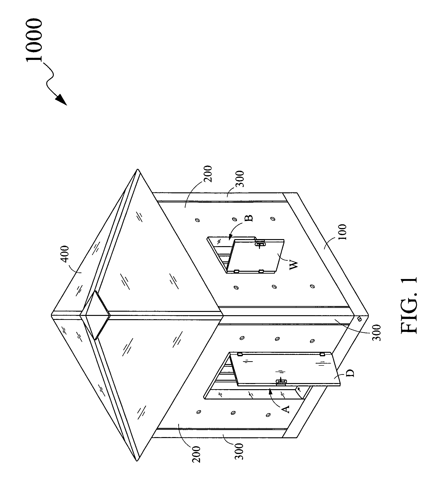
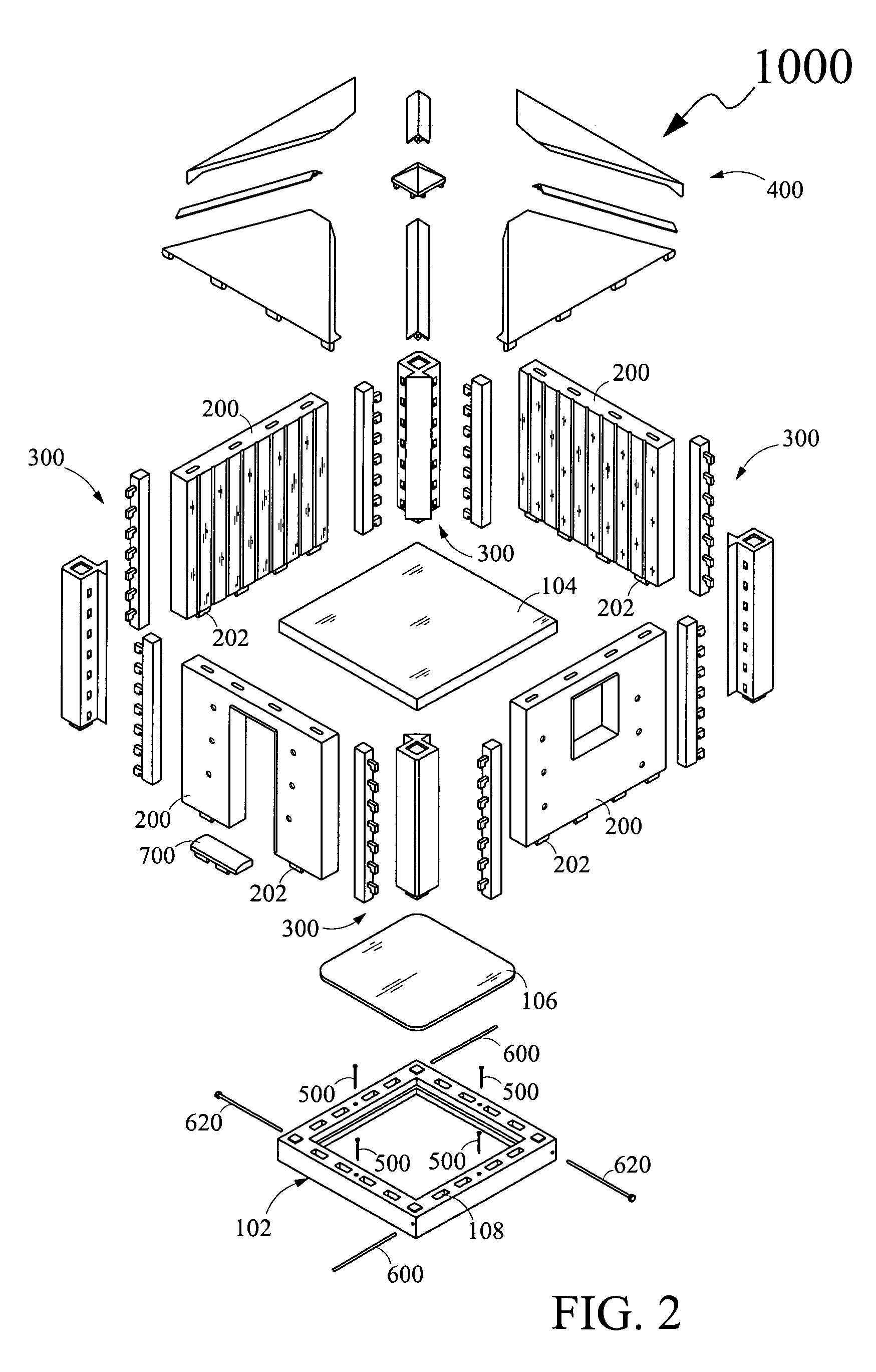
[0014]To achieve the above objects, in an aspect of the present invention, a modular building system for configuring a building structure is provided. The modular building system comprises a foundation member, a plurality of wall members, a plurality of wall-retaining members and a roofing member. The foundation member has a plurality of engaging members. Further, each of the plurality of wall members has a plurality of complementary engaging members on a bottom portion and a plurality of engagement member on a top portion. The complementary engaging members enable the wall members to be detachably attached to the foundation member by engaging with the engaging members. The attachments of the wall members and the foundation member configure a space therebetween above the foundation member with a top opening. Furthermore, the plurality of wall-retaining members is adapted to be detachably attached with the plurality of wall members. Each of the plurality of wall-retaining members is detachably attached to the foundation member. More particularly, each of the plurality of wall-retaining members extends vertically from a top surface of the foundation member, and between at least two adjacent wall members of the plurality of wall members for configuring a detachable attachment therebetween. Further, the roofing member having complementary engagement members is adapted to be detachably attached to the plurality of engagement members of the plurality of wall members providing for covering the top opening to configure the building structure.

Problems solved by technology

In present scenarios, the building construction field is generally labor and cost intensive.
Construction of a building further requires involvement of a considerable amount of time.
The wood and aluminum frame prefabrication systems are limited to low density suburban housing and where ground conditions are stable and dry.
The wood and aluminum frame prefabrication systems are not suitable to those areas where the ground conditions are erosive and wet.
In case of the ground conditions being erosive and wet, light-weight foundation of such a building structure may not withstand and may result in collapsing of the building structure, thereby resulting in injuries to individuals living in the building structure.
These prefabrication systems have not been exploited to a great extent.
More specifically, these prefabrication systems are exploited in commercial construction sectors of industry, but in case of residential construction sector of the industry, their use is very limited.
Most of the prefabrication systems include structural systems such as, walls and floors, which do not solve architectural design needs of users.
In addition to not being user or market oriented to any substantial degree, these prefabrication systems tend to be costly, require expensive erection and dismantling cost.
Due to these reasons, such prefabrication systems have been unsuitable for applications in both commercial and residential construction sectors.
Apart from the above, building structures made by such prefabricated structures suffer from several disadvantages, such as cracking due to inclement weather conditions, which result into wear and tear to the building structures and often lead to leaks, creaks and structural damage.
Further, inadequate and ineffective insulation to noise, heat and cold is one of the major problems in such building structures.
Also, existing designs of such building structures are generally of a temporary nature and may not be easily customized to meet requirements of change in sizes and places of the building structures.
Furthermore, the portability of such prefabricated structures can be another problem because of their weight, complexity of structure and the danger of rupture of the prefabricated structures while transporting.
Such prefabricated structures may not be easily and quickly erected to meet demands for such structures without a great deal of manpower, within the required time.

Method used


Image

  • Modular building system
  • Modular building system
  • Modular building system

Examples


Embodiment Construction

[0038]For a thorough understanding of the present invention, reference is to be made to the following detailed description, including the appended claims, in connection with the above-described drawings. Although the present invention is described in connection with exemplary embodiments, the present invention is not intended to be limited to the specific forms set forth herein. It is understood that various omissions and substitutions of equivalents are contemplated as circumstances may suggest or render expedient, but these are intended to cover the application or implementation without departing from the spirit or scope of the claims of the present invention. Also, it is to be understood that the phraseology and terminology used herein is for the purpose of description and should not be regarded as limiting.

[0039]The term “first”, “second”, “top”, “bottom”, “inner”, “outer” and the like, herein do not denote any order, quantity or importance, but rather are used to distinguish on...


PUM


Abstract

Disclosed is a modular building system for configuring a building structure. The modular building system includes a foundation member, a plurality of wall members, a plurality of wall-retaining members and a roofing member. The foundation member has a plurality of engaging members that engages with a plurality of complementary engaging members of wall members. The foundation member and the wall members are detachably attached as the engaging members and the complementary engaging members engage to each other and create a space with a top opening. The adjacent wall members are attached by a plurality of the wall-retaining members. Further, the wall member includes a plurality of engagement members that engages with a plurality of complementary engagement members provided on the roofing member to detachably attach the plurality of engagement members on top portion of the plurality of wall members for covering the top opening, thereby configuring the building structure.

Description

CROSS-REFERENCE TO RELATED APPLICATIONS[0001]The present invention claims priority under 35 United States Code, Section 119 on the U.S. Provisional Patent Application numbered 60 / 933,411 filed on Jun. 5, 2007, the disclosure of which is incorporated by reference.FIELD OF THE INVENTION[0002]The present invention relates to modular buildings, and more particularly, to structural elements for use in construction of the modular buildings.BACKGROUND OF THE INVENTION[0003]In present scenarios, the building construction field is generally labor and cost intensive. Construction of a building further requires involvement of a considerable amount of time. To reduce the factors such as labor, cost and time involvement in the construction of the building, prefabrication systems have been proven as one of the potential solutions. A typical prefabrication system involves prefabricated structures that are erected together to form a building structure.[0004]Existing prefabrication systems fall into...

Claims


Application Information

Patent Timeline
Patent Type & Authority Applications(United States)
IPC IPC(8): E04B1/343
CPCE04H1/1205E04B1/34315
Inventor LYONS, VICTORIASAMUEL, KITT
Owner SHELTER TECH
Learn More