
Hydraulic hybrid turbo transmission

Inactive Publication Date: 2009-12-24
MUSTAFA REZ
View PDF42 Cites 2 Cited by
  • Summary
  • Abstract
  • Description
  • Claims
  • Application Information

AI Technical Summary

Benefits of technology

[0021]It is an object of the hydraulic hybrid turbo-transmission to operate without frictional disc clutched or gears that create heat that results in a loss of energy.
[0022]It is an object of the hydraulic hybrid turbo-transmission to create a hydraulic hybrid turbo-transmission that is simpler and has fewer components than a modern automatic transmission. Only one controller is used with a few solenoid valves where the solenoids control by the transmission module (TCM) and that the transmission acts as an automatic transmission. Manual shifting can be done by operating the solenoid valves manually to act as a manual transmission or by (TCM). It is simpler in operation and less expensive than modern automatic or manual transmissions.
[0023]It is another object of the hydraulic hybrid turbo-transmission to eliminate a torque converter. The torque converter is not required in the hydraulic hybrid turbo-transmission and therefore more energy is saved from efficiency loss and weight reductions.

Problems solved by technology

Most automatic transmissions being used today normally have high fuel consumption because of the weight of the transmission, complicated system and does not meet economical driving conditions.
Most manual transmission and automatic transmission are mechanical in nature and a portion of the time the speed and torque of the transmission does not match the speed and torque that is required by a vehicle or by other means.
The transmission match the speed of the vehicle but produces more or less torque that is required by the vehicle therefore there are some energy loss.
When the multiple-disc clutches are not applied the disc will run with engine or with transmission output therefore each disc acts as disc pump and will consume energy and produce heat in the transmission.
Modern automatic transmission and manual transmissions use more than eight gears when the gears run with and without engagement with the output shaft or input shaft will act as a pump because of the teeth of the gear therefore they consume energy and produce heat in the transmission.
While these transmissions disclose power transmission they are limited to only a single speed with a multi-speed gearbox.
While this patent discloses a more variable speed system the transmission has only one gear and is therefore limited in the range of speed control.
While this application pressurizes fluid from regenerative braking the system does not provide for a two stage pump and further does not use the motor as a transmission for the drive wheels.

Method used


Image

  • Hydraulic hybrid turbo transmission
  • Hydraulic hybrid turbo transmission
  • Hydraulic hybrid turbo transmission

Examples


Embodiment Construction

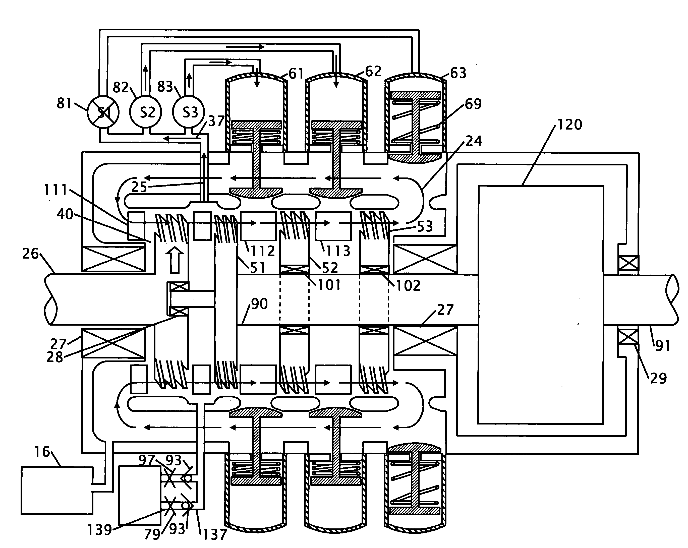
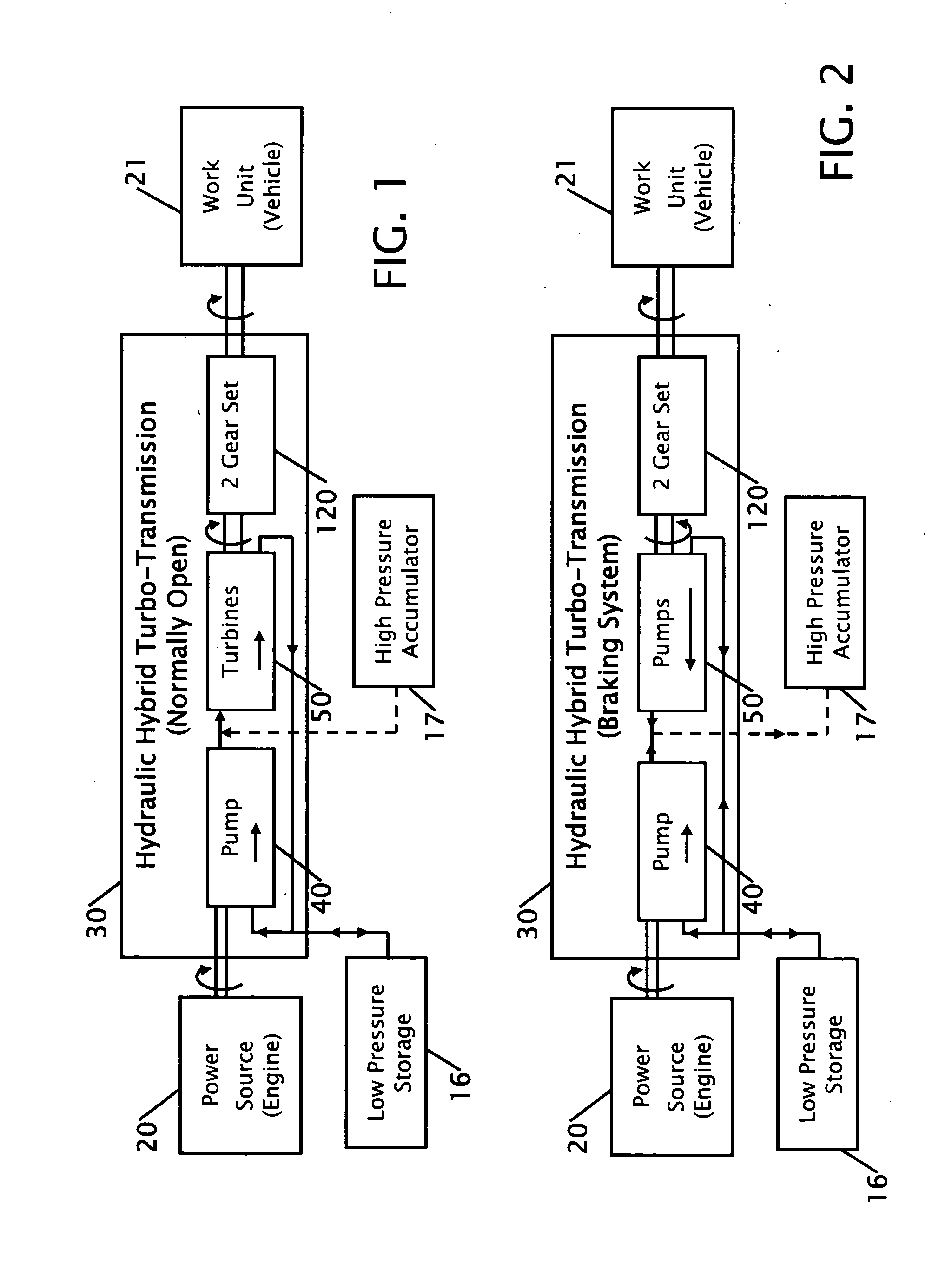
[0045]FIG. 1 shows a block diagram of the hydraulic hybrid turbo-transmission connected between an engine and a vehicle. From this block diagram a power source 20 such as an engine or motor is connected to the hydraulic hybrid turbo-transmission 30. Within the transmission is a pump 40, fluid coupled to turbines 50 and then coupled to a gear set 120. The hydraulic hybrid turbo-transmission 30 is then connected to a work unit 21 such as a vehicle. A low pressure fluid storage 16 and a high pressure fluid accumulator.

[0046]FIG. 2 shows a block diagram of the hydraulic hybrid turbo-transmission during braking. From this block diagram a power source 20 such as an engine or motor is connected to the Hydraulic hybrid turbo-transmission 30. Within the transmission is a pump 40 and turbine 50 that acts as a fluid coupled to turbines 50 that act as pumps by reverse rotation of the turbines 50 on the shaft by a second gear set. A low pressure fluid storage 16 and a high pressure fluid accumul...


PUM


Abstract

Improvements in a transmission is provided for transferring power from a power source to a work unit. The pump transfers energy received from the power source into a fluid or gas. The first turbine is fixed to output shaft, and a plurality of additional turbines are fixed on either one-way overrunning clutches or multi-disc clutches and these clutches are fixed to the output shaft and after each turbine is a multi-valves that discharges the fluid or gas. After all of the multi-stage turbines a first planetary gear set connects the transmission to the vehicle or work unit. The second planetary gear set is located between the last turbine and the first planetary gear set. During braking the planetary gear set reverses turning direction of the turbines and convert the turbines into pumps where they will pump low pressure fluid to a high pressure accumulator.

Description

CROSS REFERENCE TO RELATED APPLICATION[0001]This application is a continuation-in-part of applicant's co-pending application Ser. No. 12 / 145,469 filed Jun. 24, 2008 the entire contents of which is hereby expressly incorporated by reference herein.STATEMENT REGARDING FEDERALLY SPONSORED RESEARCH OR DEVELOPMENT[0002]Not ApplicableTHE NAMES OF THE PARTIES TO A JOINT RESEARCH AGREEMENT[0003]Not ApplicableINCORPORATION-BY-REFERENCE OF MATERIAL SUBMITTED ON A COMPACT DISC[0004]Not ApplicableDESCRIPTION[0005]1. Field of the Invention[0006]This invention relates to improvements power transmission between a motor to a vehicle and energy recovery from the breaking system. More particularly, the present hydraulic hybrid turbo transmission includes an input shaft coupled to a power source and to a pump that is configured to rotate with the input shaft. The hydraulic pump transfers energy received from the power source into a fluid. The transmission includes an output shaft and a multi-stage tur...

Claims


Application Information

Patent Timeline
IPC IPC(8): F16H45/02F16D33/00
CPCF16D33/00F16D33/02F16H41/04F16D47/06F16D47/04
Inventor MUSTAFA, REZ
Owner MUSTAFA REZ
Learn More