Torque measurement within a powertrain

a technology of torque measurement and powertrain, which is applied in the direction of work measurement, measurement devices, instruments, etc., can solve the problems of limiting direct measurement of torque in a powertrain, unable to account for the variance in performance of volume produced engines, and unable to yield instantaneous torque output of the engine at the crankshaft, so as to minimize the angular variation of the resonant frequency (or differential phase delay), minimize the angular variation of the output coupler im

Active Publication Date: 2009-12-24
TRANSENSE TECH
View PDF7 Cites 32 Cited by
  • Summary
  • Abstract
  • Description
  • Claims
  • Application Information

AI Technical Summary

Benefits of technology

[0043]Preferably, the or each strain sensor is a surface acoustic wave (SAW) device, which communicates in a non-contacting manner and which does not require active electronic components on the coupling component. Exemplary embodiments of the present invention may include a rotor and stator coupler respectively attached to the disc coupling component and a portion of the automobile that is stationary with respect to the disc coupling component, such as an engine block, for example. Each of the couplers may include transmission lines, such as microstrips, for example, with annular shapes. The couplers may be employed to communicate electromagnetic signals generated from SAWs propagated through resonators measuring torque in a non-contact manner without using slip rings. The lengths of the rotor and stator transmission lines may be configured to optimize communication for typical sizes of disc coupling components. For example, the overall length of the rotor transmission line may be circa 0.25λ and the overall length of the stator transmission line may be circa λ or an integer multiple of λ, where λ is the wavelength at the operating frequency in the rotor transmission line. In accordance with this configuration, there is no discontinuity in the field distribution in the stator transmission line. As a result, this configuration permits minimization of angular variation of the output coupler impedance, which minimizes angular variation of the resonant frequency (or differential phase delay) of the SAW sensor connected to a rotor output and measured at a stator input.
[0044]According to other exemplary embodiments, various SAW sensor interrogation methods may be employed to determine the difference between resonant frequencies for measuring torque and / or temperature, as described herein, and to activate and power SAW sensors. To improve energy efficiency, for example, different narrowband RF interrogation pulses may be respectively utilized to activate different, corresponding resonators. For example, after a search phase is conducted to detect resonant frequencies of SAW resonators, different groups of RF interrogation pulses may each have a different carrier frequency that corresponds or is near to a resonant frequency of one of the SAW resonators. In this way, energy efficiency may be improved by specifically targeting resonant frequencies of the SAW resonators using respective interrogation pulses. In accordance with another exemplary embodiment, a continuous wave interrogation signal with a variable frequency may be employed to determine resonant frequencies of resonators.
[0045]In other aspects of the present invention, the or each SAW sensor is preferably symmetrically located on its associated web, in particular on the radial centre line thereof. In this way, non-symmetrical effects, such as strains due to twisting resulting from couples acting out of plane on the coupling component are further minimised.
[0046]The webs are also preferably narrow so as to further decouple sensor output from deflections caused by unwanted forces and moments.

Problems solved by technology

This approach cannot account for the variance in performance of volume produced engines, either across the range of production tolerances or over service life, and is therefore sub-optimal.
Historically, direct measurement of torque in a powertrain has been primarily restricted to engine research and development using techniques such as:a brake dynamometer to measure engine or engine+transmission torque outputs.
However, because of rotary inertias distributed throughout the powertrain, this technique cannot yield the instantaneous torque output of the engine at the crankshaft output.strain gauged torque cells are used routinely in R&D applications.
However they are far too expensive for use in customer vehicles.
Such space is at a premium in production powertrains and may be unavailable in systems incorporating automatic transmissions.
In addition magneto-elastic sensors are susceptible to stray magnetic fields which abound in production vehicles due to multiple electric motors and solenoids.
However, a flexible disk coupling component such as a flexplate, in its normal duty, is potentially subject to three forces and two couples apart from the desired couple (i.e. in-plane torque), and these extraneous loads can reduce the accuracy of the torque measured using a strain sensor mounted on the disk.
The problem of measuring torque in a flexplate (a standard automotive component which transfers torque from the crankshaft to the torque converter) is that the flexplate must be flexible (compliant) with regard to axial loading and to out-of-plane bending but stiff in torsion.
The prior art has not been able to achieve this goal.
However the reliable and cost effective provision of such torque sensors in automotive applications has thus far been problematic.
For example, in an automotive crankshaft or gearbox output shaft, there is typically either no available physical space on the shaft in which to locate such a torque sensor or the strain field is inappropriate—either too low in strain or too high in strain gradient.

Method used


Image

  • Torque measurement within a powertrain
  • Torque measurement within a powertrain
  • Torque measurement within a powertrain

Examples


Embodiment Construction

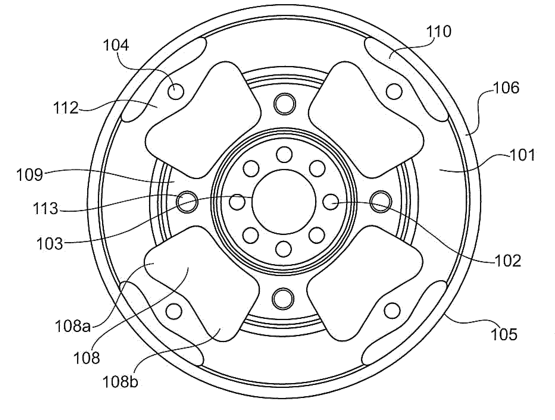
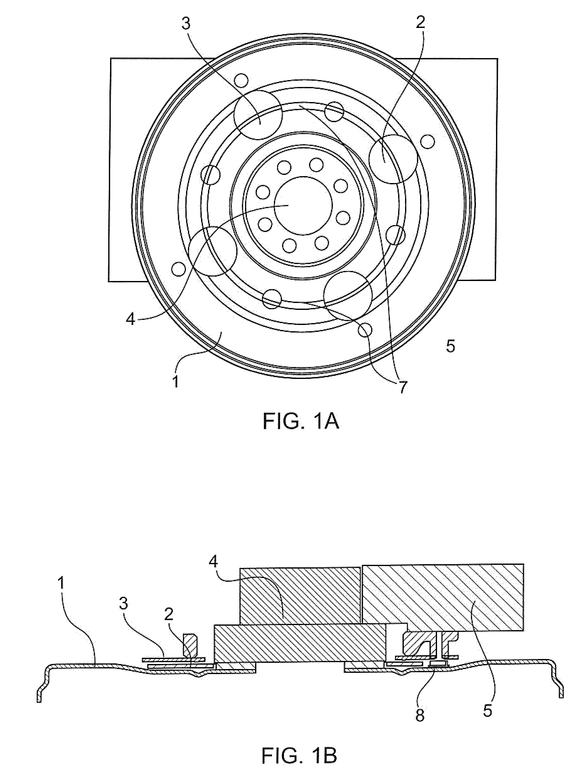
[0072]Referring to FIG. 1a, there is shown a flexplate 1, essentially a diaphragm which connects the crankshaft and the torque converter in a typical powertrain with automatic transmission, which is mounted on a crankshaft 4 which extends through an engine block 5. The flexplate is configured with cutouts to provide the required flexibility, forming spokes 7 therebetween, and, as shown in FIG. 1b, in the illustrated example a SAW sensor 8 is fastened to the engine block side of one of the spokes 7 for measuring the local strain field on the surface of the spoke, which is in turn proportional to the torque within the crank shaft 4. Also attached on the engine side of the flexplate 1 is a rotating coupler 2 which rotates with the flexplate and communicates with a stationary coupler 3 fastened to the engine block 5 for wireless transmission of signals from the SAW sensor. The stationary coupler, in the illustrated embodiment, is fastened to the block so as to maintain a small but consi...


PUM

PropertyMeasurementUnit
temperatureaaaaaaaaaa

Abstract

Aspects of the present invention are directed to using surface acoustic wave (SAW) sensors mounted on a disc coupling component in a powertrain to measure the torque generated by an automobile engine. The sensor may be positioned and oriented on the disc coupling component so that the phase velocities of SAWs propagating through active elements of the SAW sensors are aligned with principal strain components due to torque in the disc coupling component. The torque may be calculated by determining the difference between resonant frequencies of the active elements to suppress common-mode interference factors. In addition, SAW resonant frequencies may be communicated in a non-contacting manner by utilizing rotary and stationary couplers employing radio frequency (RF) signals. Moreover, SAW sensors may be activated and interrogated by employing targeted RF pulses having different carrier frequencies at or near respective resonant frequencies of each resonator in a SAW sensor.

Description

CROSS-REFERENCE TO RELATED APPLICATIONS[0001]This application is a Continuation-in-Part of U.S. patent application Ser. No. 11 / 939,242 filed on Nov. 13, 2007, which is a Continuation-in-Part of International Application PCT / GB2005 / 003118 filed on Aug. 8, 2005 which claims priority from GB Application 0418271.3 filed on Aug. 16, 2004 and International Application PCT / GB2007 / 000824 filed on Mar. 9, 2007 which claims priority from GB Application 0605240.1 filed on Mar. 15, 2006.BACKGROUND OF THE INVENTION[0002]1. Field of the Invention[0003]The present invention relates to methods of measuring torque within a powertrain as well as to apparatus for carrying out such methods, and more particularly to such an assembly incorporating a sensor for measuring torque transmitted through the coupling plate.[0004]2. Prior Art[0005]Modern internal combustion engines for automobiles, utilise engine management systems which rely on dynamometer derived data for torque output as measured on a relative...

Claims


Application Information

Patent Timeline
Patent Type & Authority Applications(United States)
IPC IPC(8): G01L3/04
CPCG01L3/1428
Inventor LOHR, RAYMOND DAVIDKALLNIN, VICTOR ALEXANDROVICHBECKLEY, JOHN PETERLEIGH, ARTHUR JOHNBOWN, GEORGE EDWARD ANDREWVILE, DAVID DANIEL GEORGE
Owner TRANSENSE TECH
Why Eureka
Try Eureka