Retentive concrete material

a concrete and reinforcement technology, applied in the field of reinforcement concrete, can solve the problems of structural degradation of the structure or component, prone to breakage of the thermo-insulating cladding of the concrete, and the creation of attachment regions after-the-fact requires expensive workarounds or inferior/substandard attachment alternatives, and achieves superior performance and superior performan

Inactive Publication Date: 2009-12-24
RODGERS MICHAEL S
View PDF10 Cites 16 Cited by
  • Summary
  • Abstract
  • Description
  • Claims
  • Application Information

AI Technical Summary

Problems solved by technology

However the construction of such components features require either on or off site construction.
This construction approach presents the constructor / builder with unique challenges in lifting and moving the large prefabricated modular components to the final position at the construction site.
Whether poured-in-place or constructed from pre-fabricated components (large or small), the constructor / builder is faced with the challenge of making an attachment to the concrete surface with penetrating attachment devices such as nails, spikes, screws, bolts, lag screws, drift pins, staples, rivets and metal connectors of various types (like metal plate connectors).
Such penetrating attachment devices when driven into harden concrete typically are not retained and further cause cracking, and structural degradation of the structure or component.
Similarly, the thermo-insulative cladding of a PICF is prone to tear outs when receiving a penetrating attachment device.
As can be appreciated, creating attachment regions after-the-fact require expensive work arounds or inferior / substandard attachment alternatives, such as gluing or other adhesive means.
As can be appreciated, additions after-the-fact require cutting the concrete or making work arounds, both of which are very expensive.

Method used


Image

  • Retentive concrete material
  • Retentive concrete material
  • Retentive concrete material

Examples


Embodiment Construction

[0021]As required, detailed embodiments of the present invention are disclosed herein; however, it is to be understood that the disclosed embodiments are merely exemplary of the invention that may be embodied in various and alternative forms. The figures, if any, are not necessarily to scale, some features may be exaggerated to show details of particular components. Therefore, specific structural and functional details disclosed herein are not to be interpreted as limiting, but merely as a basis for the claims and as a representative basis for teaching one skilled in the art to variously employ the present invention.

[0022]Furthermore, elements may be recited as being “coupled”; this terminology's use anticipates elements being connected together in such a way that there may be other components interstitially located between the specified elements, and that the elements may be connected in fixed or movable relation one to the other.

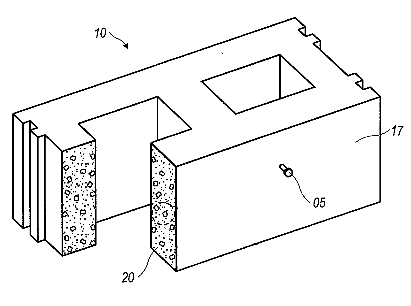
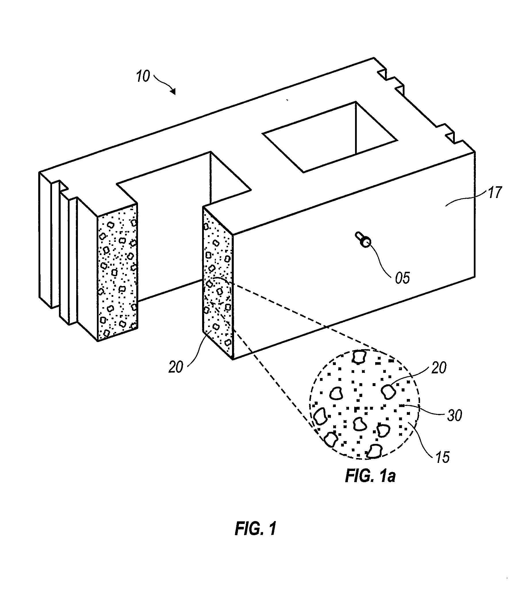
[0023]The present invention comprises a retentive co...


PUM

PropertyMeasurementUnit
non-metallicaaaaaaaaaa
structureaaaaaaaaaa
dimensionsaaaaaaaaaa

Abstract

A concrete material with fastener retentive qualities that can be varied to approximate the fastening holding characteristics of a selected variety of wood species or composite wood products comprising a mixture of cement binder, aggregate, and pliable material in the following volumetric ratio of approximately one-half (½) to one (1) part cement binder to approximately two (2) parts aggregate to approximately two (2) to five (5) parts pliable additive material. Cement binder can be Portland Cement, fly ash, slag and a combination thereof. Aggregate can be sand, gravel, stone, crushed rock, and a combination thereof. Pliable material can be plastic, cellulose, crumb rubber, and a combination thereof in pelletized, grannular or powdered form.

Description

TECHNICAL FIELD[0001]This invention relates generally to concrete used in the construction industry. More particularly, it relates to an improved concrete material that can be uniformly shaped into building components capable of receiving and nails, screws, bolts, lag screws, drift pins, staples and metal connectors of various types.BACKGROUND ART[0002]In general, concrete has been used to construct walls and other structural building components, such as slabs, panels, piers, columns and posts. However the construction of such components features require either on or off site construction.[0003]Construction that requires walls or other building components, such as slabs, panels, piers, columns and posts are typically carried out through the use of large prefabricated modular concrete components or pouring a concrete slurry into a temporary form erected on site (e.g. pour-in-place). This temporary or removable form must be constructed to hold a concrete slurry in place until cured. A...

Claims


Application Information

Patent Timeline
Patent Type & Authority Applications(United States)
IPC IPC(8): C04B28/08C04B28/04C04B28/02C04B14/06C04B14/00
CPCC04B2111/30C04B28/04C04B14/06C04B16/08C04B18/08C04B18/14C04B18/20C04B18/22C04B18/24Y02W30/91
Inventor RODGERS, MICHAEL S.
Owner RODGERS MICHAEL S
Why Eureka
Try Eureka