Vehicular Movement Electricity Converter Embedded Within A Road Bumb

a technology of electric converter and vehicular movement, applied in the direction of machines/engines, traffic signals, roads, etc., can solve the problems of drivers slowing down in potentially dangerous places, causing significant obstacles to passing vehicles, and causing drivers to slow down or risk damage to their vehicles

Inactive Publication Date: 2009-12-24
INNOVATIVE PATENTS
View PDF21 Cites 32 Cited by
  • Summary
  • Abstract
  • Description
  • Claims
  • Application Information

AI Technical Summary

Benefits of technology

[0006]The disclosed system takes the idea of utilizing on-road electricity generators further. It is observed that the traditional vehicular movement energy converters create a substantial obstacle for the passing vehicles. Any driver passing over such a converter is required to slow down or risk damaging his or her vehicle. The disclosed system transforms this disadvantage into an advantage by embedding the vehicular movement converter within a road hump.

Problems solved by technology

It is observed that the traditional vehicular movement energy converters create a substantial obstacle for the passing vehicles.
Any driver passing over such a converter is required to slow down or risk damaging his or her vehicle.
The humps make drivers slow down in potentially dangerous places.

Method used


Image

  • Vehicular Movement Electricity Converter Embedded Within A Road Bumb
  • Vehicular Movement Electricity Converter Embedded Within A Road Bumb
  • Vehicular Movement Electricity Converter Embedded Within A Road Bumb

Examples


Embodiment Construction

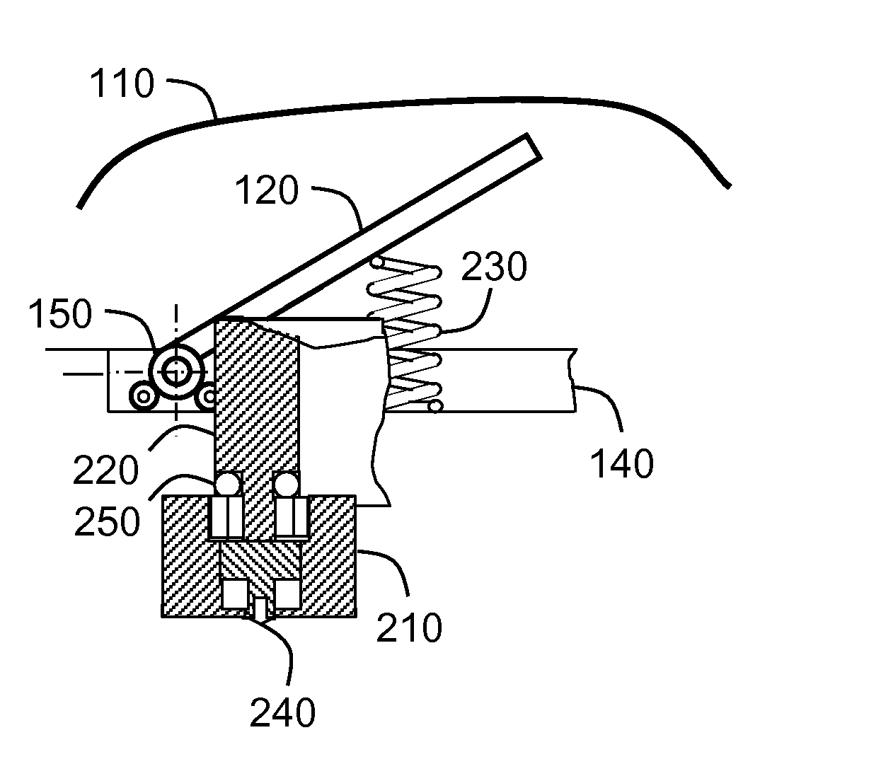
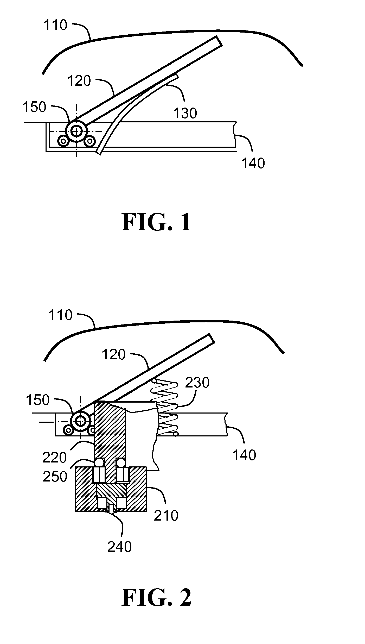
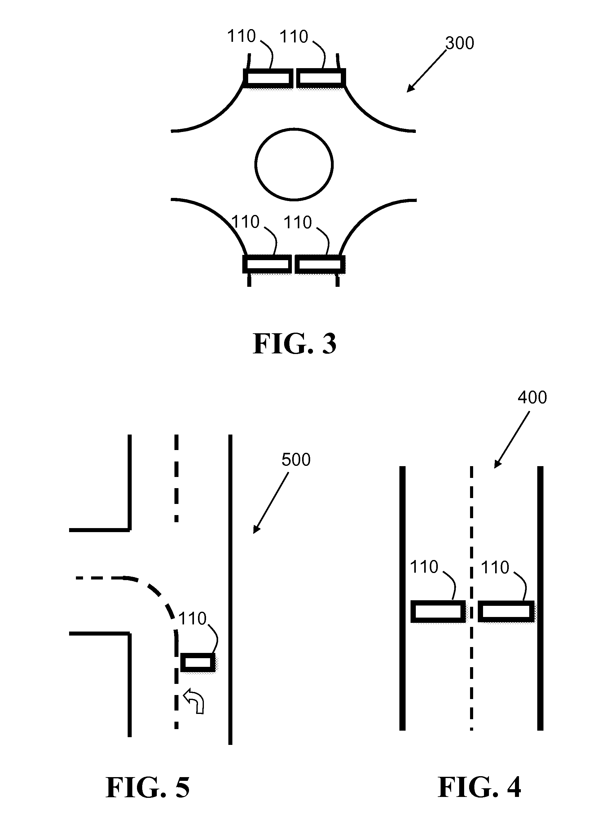
[0021]FIG. 1 shows a schematic diagram of the system according to the present invention without the electrical conversion means. The system comprises an arced cover strip 110 that runs across a traffic lane or multiple lanes. The cover strip 110 is mounted upon a housing 140 that is embedded within the road, directly under the cover strip. The cover strip 110 is abutted upon a wing 120 that is attached to an axis of rotation 150 also located within the housing 140. The upper end of the wing 120 touches the cover strip above the road level. The wing 120 is also connected to a spring 130, such as a compression spring. Whenever the cover strip 110 is pressed down, the wing 120 rotates around the axis 150 and is subsequently returned to its original position by the spring 130.

[0022]According to some embodiments of the invention, the wing 120 may be comprised of a plurality of adjacent wings that may be connected together in a telescopic manner.

[0023]FIG. 2 shows a schematic diagram of t...


PUM


Abstract

A system for converting vehicular movement into electricity while serving as a road hump at the same time. The linear motion of the vehicles is transformed by the device into rotational motion and finally converted into electric power. The system comprises a semi-flexible cover strip lying across the path of vehicular traffic, covering the rest of the system, which is encapsulated within a housing embedded in the ground. The cover is connected to a generator via a wing or wings and a mechanism or mechanisms comprising a fly wheel, a rotor, a stator and a clutch. Passing vehicles push the cover strip down, causing the wings to depress, and engaging a clutch that transfers a rotational motion to the rotor, eventually, the rotor drives an electromagnetic generator. The electromagnetic generator converts the rotational motion of the rotor into electrical power.

Description

CROSS-REFERENCE TO RELATED APPLICATION[0001]This application is a National Stage of International Application No. PCT / IL2007 / 001165 filed Sep. 20, 2007, which claims priority based on Provisional Patent Application No. 60 / 845,772 filed Sep. 20, 2006, both of which are incorporated herein by reference in their entirety.FIELD OF THE INVENTION[0002]The present invention relates generally to kinetic-electrical energy conversion systems, and more particularly to the conversion of the energy of passing vehicles into electricity.BACKGROUND OF THE INVENTION[0003]Traditional methods of converting kinetic energy into electricity are known to be embedded in roads for generating electricity from passing vehicles. U.S. Pat. No. 6,767,161 which is incorporated herein by reference in its entirety discloses such system. The system generates power from the passage of motor vehicles. The vehicular movement is transformed into rotational energy of a turbine located on the side of the road.[0004]U.S. P...

Claims


Application Information

Patent Timeline
Patent Type & Authority Applications(United States)
IPC IPC(8): H02K7/18E01F9/529
CPCE01C9/00E01F13/123H02K7/1853H02K7/06F03G7/08
Inventor CHEN, RON
Owner INNOVATIVE PATENTS
Why Eureka
Try Eureka