Kit servomotor

a servomotor and kit technology, applied in the direction of dynamo-electric machines, yielding couplings, electrical apparatus, etc., can solve the problems of increasing the force, minimizing the mass of the rotary encoder system, and the vibration of the entire system

Inactive Publication Date: 2009-12-24
SICK STEGMANN
View PDF7 Cites 13 Cited by
  • Summary
  • Abstract
  • Description
  • Claims
  • Application Information

AI Technical Summary

Problems solved by technology

If, in a manner known to the prior art, the rotor of the electromotor and the encoder shaft are joined by means of a bellows connection, problems arise that are difficult to solve, particularly because, in the case of angular acceleration, the inertia of the rotating parts of the rotary encoder that are connected to the encoder shaft results in a torque which may cause resonance vibrations in the entire system.
This is particularly a source of problems when a high normal rigidity is required

Method used


Image

  • Kit servomotor
  • Kit servomotor

Examples


Embodiment Construction

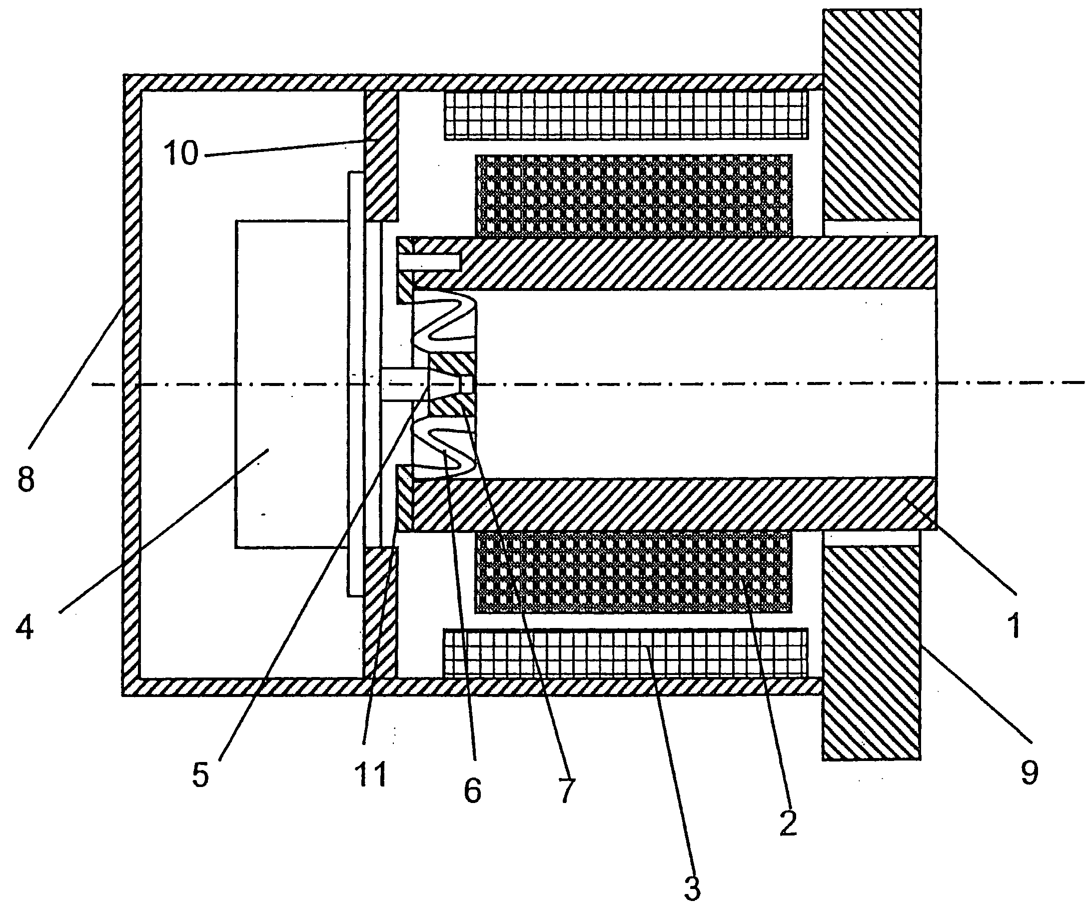
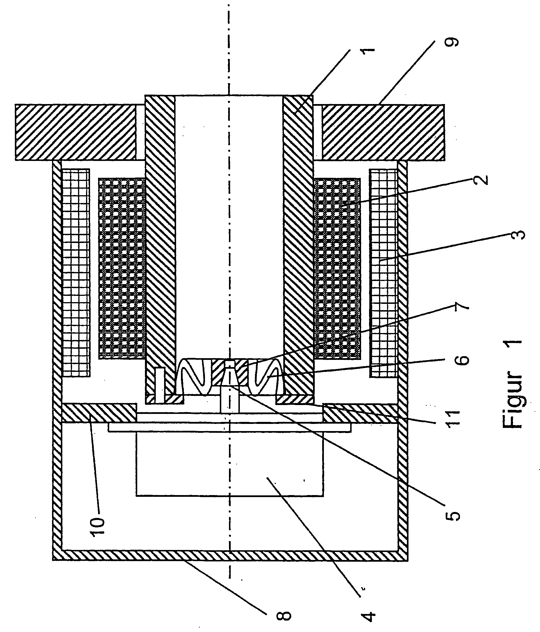
[0008]The invention is based on the problem of creating a kit servomotor which couples the rotary encoder to the electromotor in a cost-effective manner and which, in particular, is well-suited to the special demands placed on such kit servomotors.

[0009]The invention solves this problem with a kit servomotor.

[0010]Other advantageous embodiments of the invention are also described below.

[0011]Generally speaking, the kit servomotor according to the invention involves a motor with a large diameter, which is also known as a torque motor. These kit motors with a large diameter are generally not designed for high rotational accelerations like standard servomotors, whose performance is based on rotary speed and which therefore always operate with a gear. The invention utilizes the relatively low rotary acceleration which is a feature of such kit motors to provide a cost-effective design for the rotary encoder coupling. The design of the rotor as a hollow shaft, which is customary in these ...


PUM


Abstract

A kit servomotor consists of an electromotor and a rotary encoder. The electromotor has a motor stator (3, 8) and a rotor (1), which is positioned in unsupported fashion in the motor stator. The motor stator (3, 8) and the rotor (1) can be installed on the output end. The rotor (1) is designed as a hollow shaft, at least on its end opposite the end used for installation. The rotary encoder is attached to the electromotor on the end opposite the installation end and has a stator unit (4) and an encoder shaft (5). The stator unit (4) is connected to the motor stator (3, 8). The encoder shaft 5 is connected to the rotor (1) using a coupling that is isogonal with respect to the angle of rotation, but elastic in the radial and axial directions. At its motor end, which is coaxial to the hollow shaft of the rotor (1), the encoder shaft (5) has an outer diameter that is smaller than the inner diameter of the hollow shaft. The coupling is axially flat in design and bridges the annular gap between the outer diameter of the encoder shaft (5) and the inner diameter of the hollow shaft of the rotor (1).

Description

BACKGROUND OF THE INVENTION[0001]The invention relates to a kit servomotor.[0002]Servomotors consist of an electromotor and a device for measuring angular rotation, which in the following is referred to as a rotary encoder. The electromotor has a motor stator and a rotor, such that the rotary encoder measures the angle of rotation, or a rotor magnitude that is dependent on the angle of rotation, in relation to the motor stator or the motor housing. To this end, an encoder shaft belonging to the rotary encoder is coupled to the rotor of the electromotor, and a stator unit belonging to the rotary encoder is coupled to the motor stator. The coupling must create an isogonal connection that is as true as possible, in order to provide an exact angular measurement. At the same time, it must be able to accept the radial and axial alignment tolerances that are unavoidable with the installation of the rotary encoder on the electromotor.[0003]Two basic variations are known for coupling the rot...

Claims


Application Information

Patent Timeline
IPC IPC(8): H02K11/00
CPCH02K11/0015H02K11/21F16D3/76F16D3/78
Inventor SIRAKY, JOSEF
Owner SICK STEGMANN
Why Eureka
Try Eureka