
Aerodynamic bearing assembly for spindle motor for hard disk drives

a technology of bearing assembly and hard disk drive, which is applied in the direction of elastic bearings, bearing unit rigid support, instruments, etc., can solve the problems of reducing the assembly capacity driving at a high speed with a strict rotational precision, and generating noise and vibration, so as to improve the structural safety of the spindle motor

Inactive Publication Date: 2007-11-27
G&W TECH
View PDF8 Cites 2 Cited by
  • Summary
  • Abstract
  • Description
  • Claims
  • Application Information

AI Technical Summary

Benefits of technology

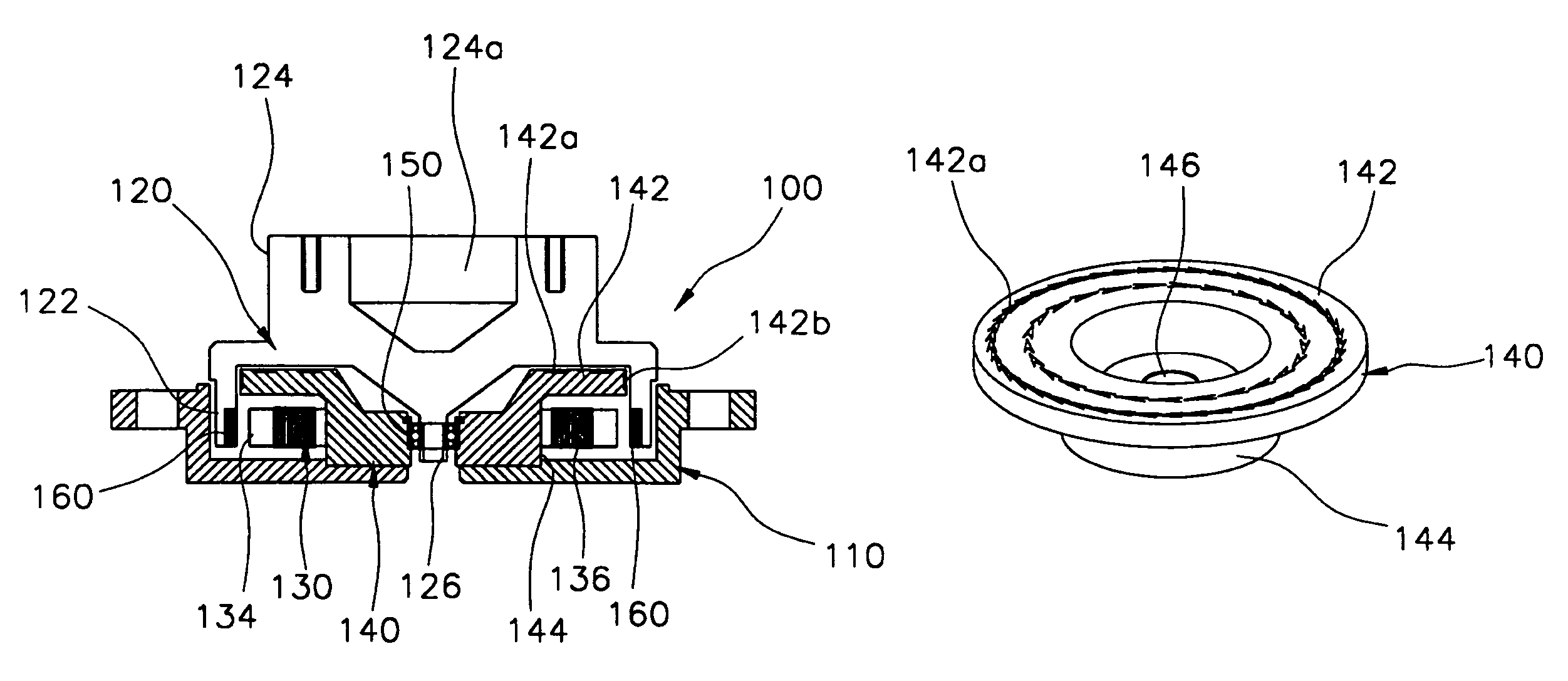
[0015]Therefore, the present invention has been made in view of the above-mentioned problems, and it is an object of the present invention to provide an aerodynamic bearing assembly for a spindle motor for hard disk drives, in which a rotatable hub of the spindle motor for hard disk drives is adapted not only to be pivoted in both radial and thrust directions by the ball bearing coming into direct contact with the center of the hub so as to perform rotation according to the rotational principle of the whirligig, but also to be subjected to the thrust load through the aerodynamic bearing assembly with the air groove(s) without being in contact with it, so that the hub can maintain a rotational center without mechanical contact resulting in noise and starting failure of the aerodynamic bearing assembly during an initial starting (during low-speed rotation).
[0016]It is another object of the present invention to provide an aerodynamic bearing assembly for a spindle motor for hard disk drives, in which a hub, which is designed to have a conical structure like a whirligig and a rotatable point-contact supporting structure through the ball bearing, is combined with the aerodynamic bearing having at least one air groove, which is formed on at least one of the upper horizontal surface of the main bearing body of the aerodynamic bearing, the outer circumferential surface of the main bearing body of the aerodynamic bearing, the lower horizontal surface of the hub and the inner circumferential surface of the cylindrical section of the hub, so that rotational rigidity of the bearing against disturbance during high-speed rotation rather than during low-speed rotation as well as the capability of rotating without a slant are improved, and thus an excellent rotational precision can be obtained.
[0017]It is yet another object of the present invention to provide an aerodynamic bearing assembly for a spindle motor for hard disk drives, in which a hub is designed to have a conical structure like a whirligig and a rotatable point-contact supporting structure through the ball bearing, so that even though static electricity is generated by friction between the air caused by a high-speed rotation and the platter, the static electricity can be discharged through the ball bearing, thus improving a structural safety of the spindle motor.

Problems solved by technology

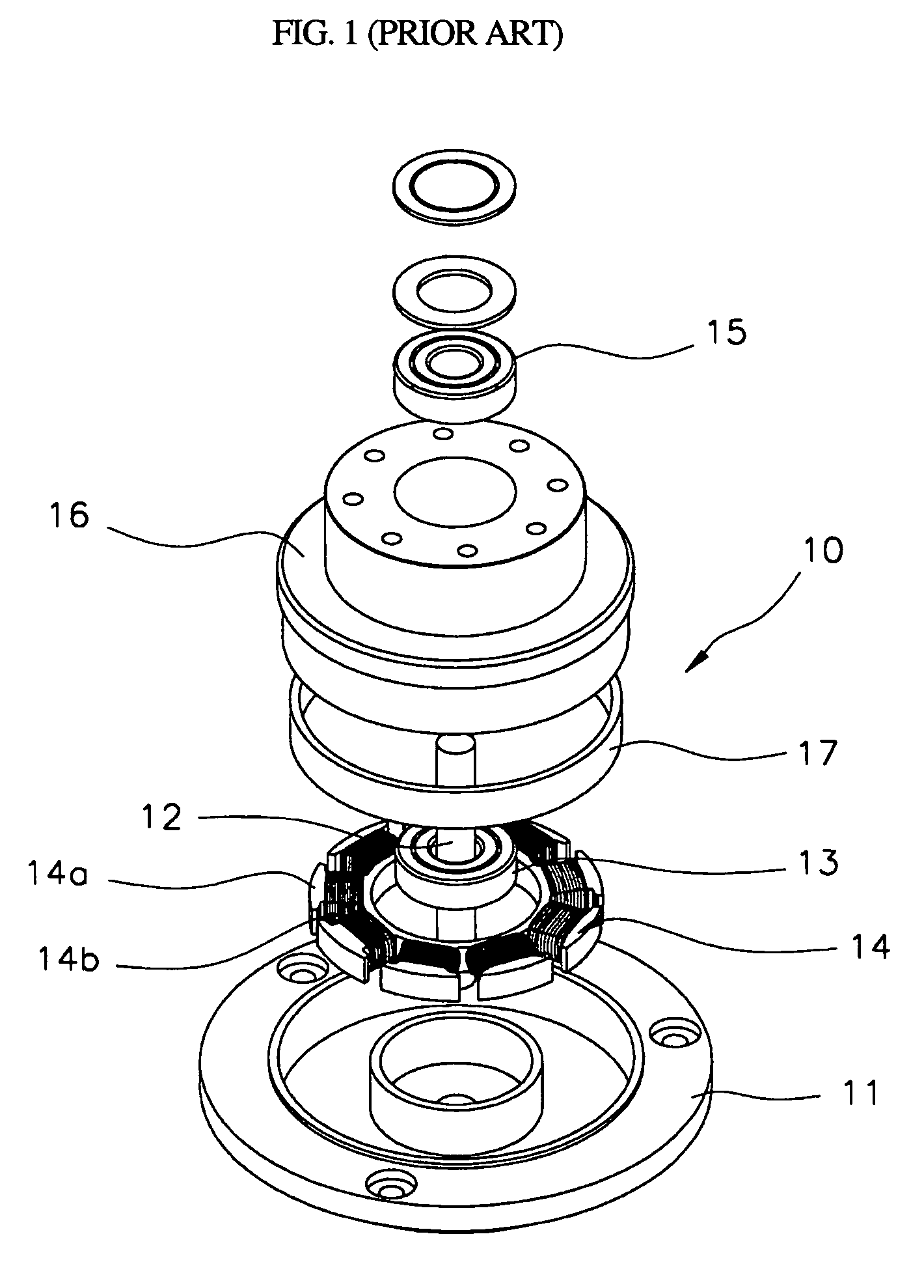
However, the construction wherein the hub 16 rotates using the first and second ball bearings 13 and 15 makes it impossible to drive at a high speed with a strict rotational precision, which results in generating noise and vibration when the ball bearing rotates at a high speed.
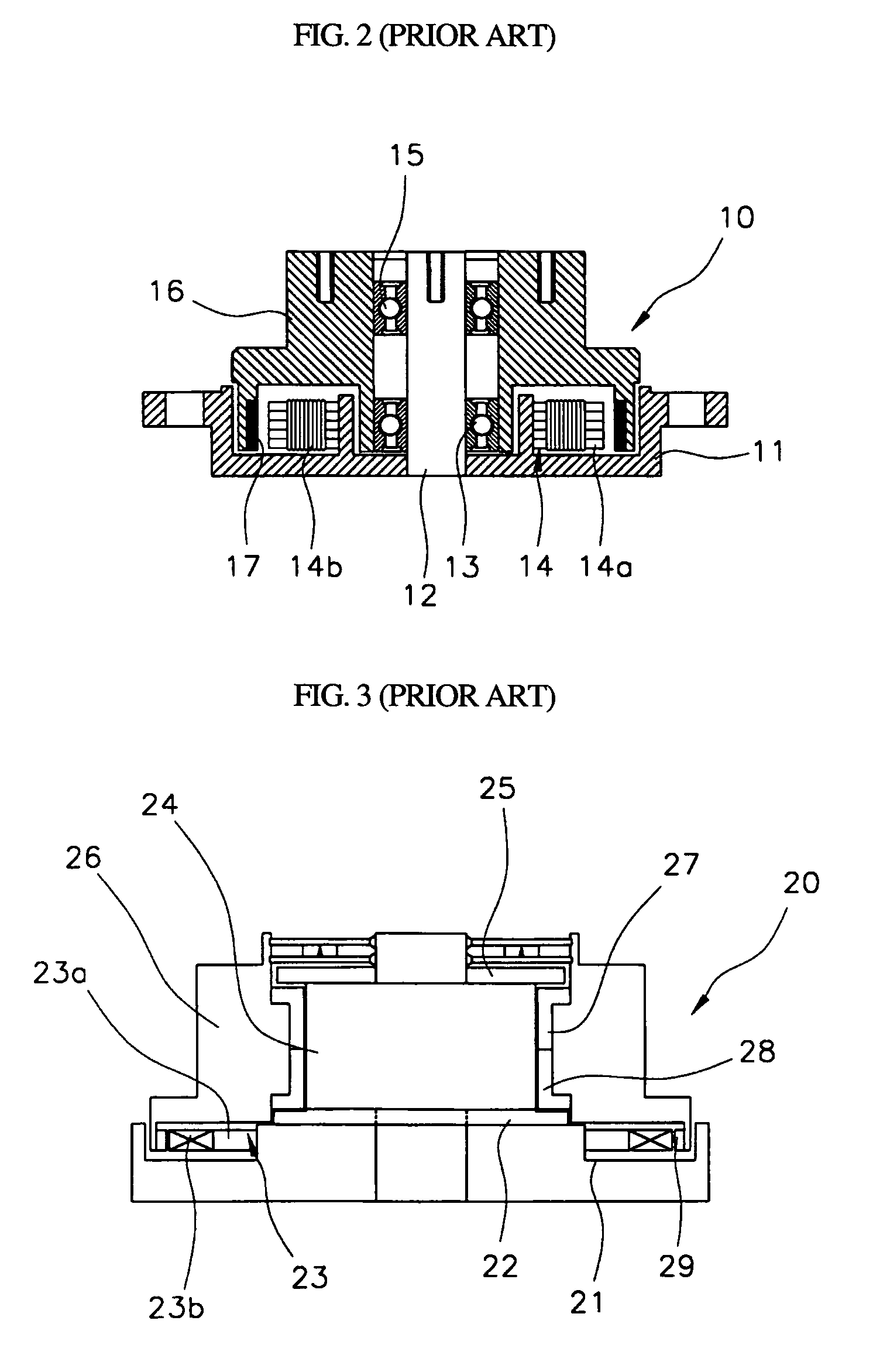
Therefore, there are problems in that the spindle motor has a reduced assembly capability and has a difficulty in constantly maintaining a constant thickness of the air gap.
Therefore, during initial starting, the spindle motor is subjected to malfunction, attrition losses of the aerodynamic bearings as well as the first and second ball bearings, noise and vibration, all of which are caused by friction.

Method used


Image

  • Aerodynamic bearing assembly for spindle motor for hard disk drives
  • Aerodynamic bearing assembly for spindle motor for hard disk drives
  • Aerodynamic bearing assembly for spindle motor for hard disk drives

Examples


Embodiment Construction

[0039]In order to accomplish the above-mentioned objects, there is provided an aerodynamic bearing assembly employed in a spindle motor for hard disk drives, the spindle motor including a base, a hub, a stator and a permanent magnet, the base serving as a lower portion of the spindle motor, the hub being rotatably fitted on the base and able to fixedly mount a platter, the stator being formed with a plurality of cores wound around by one or more coils along an outer circumference of the stator and being formed with an open press-fit portion at the center of the stator. The permanent magnet is fitted on an inner circumferential surface of the hub and generates a magnetic field in cooperation with the coil. The aerodynamic bearing assembly comprises an aerodynamic bearing including a main bearing body formed in a concentric disk shape to serve as an upper portion of the aerodynamic bearing, and an auxiliary bearing body integrally formed on a lower portion of the main bearing body and...


PUM

PropertyMeasurementUnit
magnetic fieldaaaaaaaaaa
aerodynamic pressureaaaaaaaaaa
depthaaaaaaaaaa

Abstract

Disclosed is an aerodynamic bearing assembly for a spindle motor for hard disk drives, in which a hub of the spindle motor is pivoted in both radial and thrust directions by the ball bearing, which directly contacts the center of the hub, to perform rotation according to the rotational principle of a whirligig, and is subject to the thrust load through the aerodynamic bearing assembly with air groove(s) without being in contact with it, so that the hub maintains a rotational center without mechanical contact resulting in noise and starting failure of the assembly during an initial starting (low-speed rotation). The assembly includes air grooves, the air groove generating aerodynamic pressure between the hub and the aerodynamic bearing while the hub rotates.

Description

FIELD OF INVENTION[0001]The present invention relates to a spindle motor for hard disk drives. More particularly, the present invention relates to an aerodynamic bearing assembly for a spindle motor for hard disk drives capable of pivoting a lower portion of a hub in both radial and thrust directions through use of a ball bearing, which comes into direct contact with the lower portion of the hub, so that a rotational center of the hub can be maintained without mechanical contact resulting in noise and starting problems of the aerodynamic bearing assembly during an initial starting (during low-speed rotation).BACKGROUND ART[0002]Generally, a hard disk drive functions as an auxiliary memory unit of a computer, and is comprised of a platter, a head, a spindle motor, a head arm and a printed circuit board. The hard disk drive helps to operate the system of a computer either by reading out and regenerating information stored at the platter through the head or by writing new information o...

Claims


Application Information

Patent Timeline
Patent Type & Authority Patents(United States)
IPC IPC(8): F16C21/00F16C27/00F16C17/04F16C33/10G11B19/20
CPCF16C17/026F16C17/045F16C33/107G11B19/2009F16C17/107F16C2370/12G11B19/20
Inventor KIM, SANG UKMYUNG, BEOM YOUNG
Owner G&W TECH
Learn More