
Apparatus for preventing automotive pedal from being pushed rearward

a technology for automobile pedals and accessories, applied in the direction of mechanical control devices, instruments, foot actuation initiations, etc., can solve the problems of increased impact force, increased degree of foot and lower body injury of drivers, and increased impact force, so as to reduce the overall weight of the vehicle pedal, and improve the rigidity of the vehicle pedal

Active Publication Date: 2016-04-26
SL CORP
View PDF16 Cites 2 Cited by
  • Summary
  • Abstract
  • Description
  • Claims
  • Application Information

AI Technical Summary

Benefits of technology

The present invention provides an apparatus for preventing a vehicle pedal from being pushed rearward that reduces the overall weight of the pedal by forming a cavity and a rotating member made of a lightweight material such as plastics. This reduces the manufacturing costs and prevents the rotation of the pedal arm from being hindered by the weight of the arm. Additionally, a reinforcing member made of metal material can be added to increase the rigidity of the rotating member. The apparatus facilitates the formation of a rotating member and helps in the overall weight reduction of the vehicle pedal.

Problems solved by technology

The force from the impact caused by the collision, for example, a head-on collision, is applied to the driver's foot on the brake pedal, and may thus cause severe injury to the driver's foot and to the rest of the driver's lower body.
In addition, when a serious collision occurs, the dash panel is pushed toward the passenger compartment of a vehicle and the impact force is increased, and since the brake pedal is positioned adjacent to the driver's foot, the degree to which the foot and the lower body of the driver are injured may further increase.
However, this type of apparatus has a serious safety-related defect since the brake pedal is formed of a highly rigid metal material to improve the structural rigidity of the brake pedal, the weight of the brake pedal may be increased to the extent that the brake pedal may not be properly released from the mounted position and may thus cause injury to the driver.

Method used


Image

  • Apparatus for preventing automotive pedal from being pushed rearward
  • Apparatus for preventing automotive pedal from being pushed rearward
  • Apparatus for preventing automotive pedal from being pushed rearward

Examples


Embodiment Construction

[0020]Advantages and features of the present invention and methods of accomplishing the same may be understood more readily by reference to the following detailed description of exemplary embodiments and the accompanying drawings. The present invention may, however, be embodied in many different forms and should not be construed as being limited to the exemplary embodiments set forth herein. Rather, these exemplary embodiments are provided so that this disclosure will be thorough and complete and will fully convey the concept of the invention to those skilled in the art, and the present invention will only be defined by the accompanying claims. Like reference numerals refer to like elements throughout the specification.

[0021]It is understood that the term “vehicle” or “vehicular” or other similar term as used herein is inclusive of motor vehicles in general such as passenger automobiles including sports utility vehicles (SUV), buses, trucks, various commercial vehicles, watercraft i...


PUM


Abstract

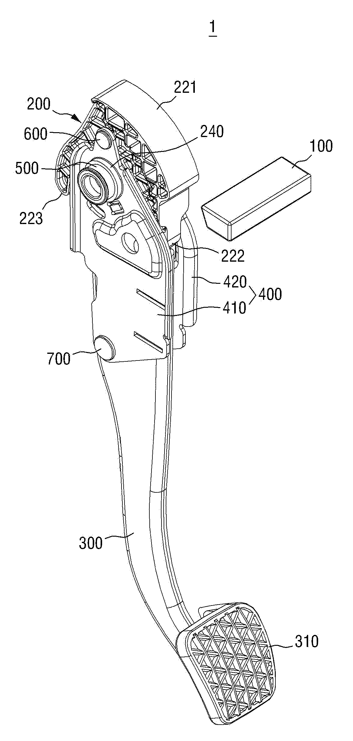
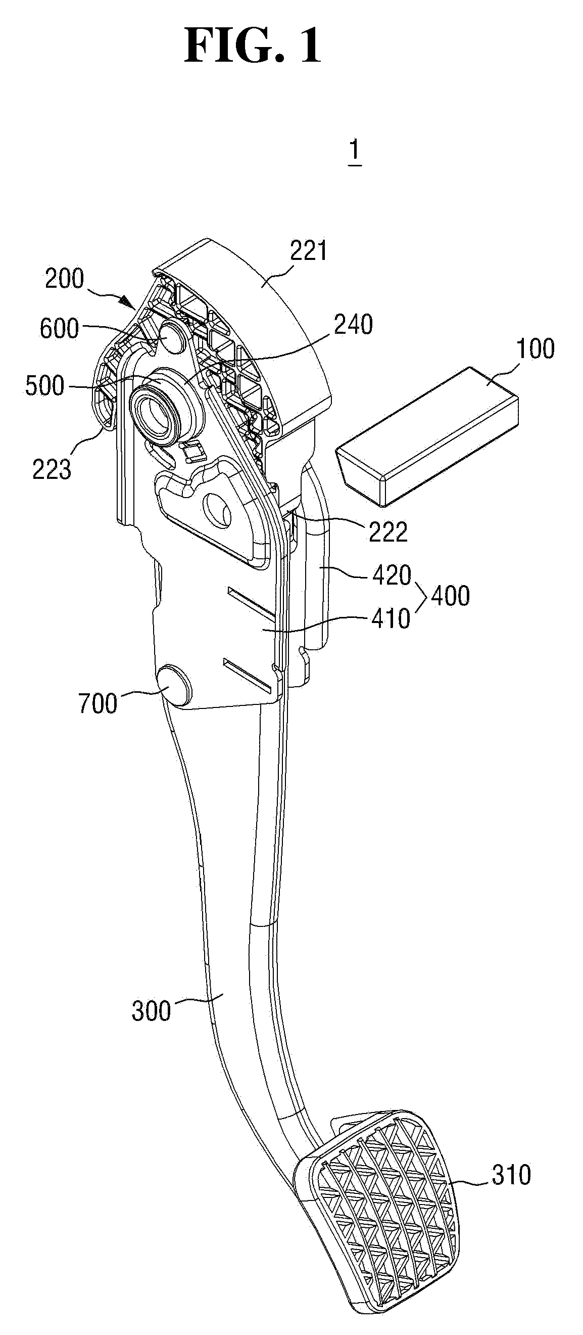
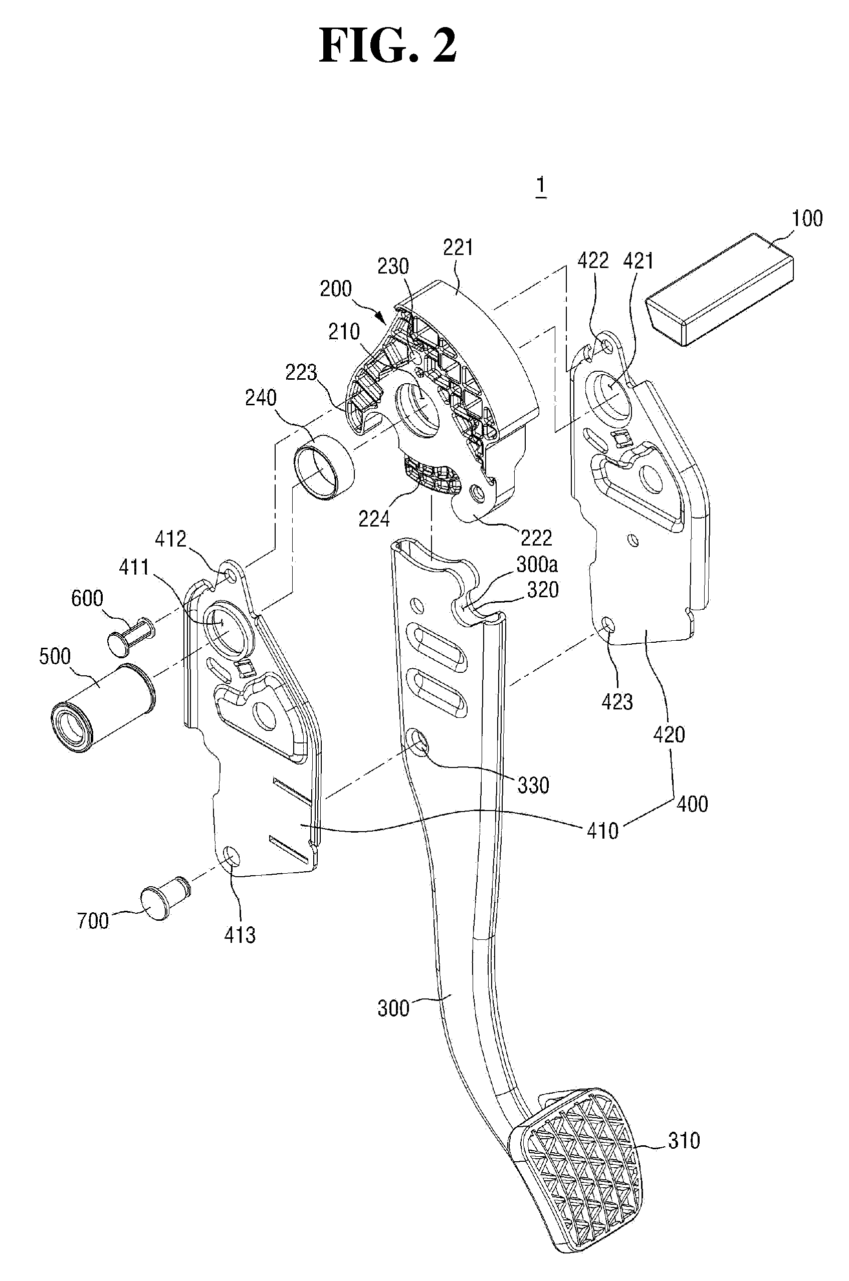
An apparatus for preventing a vehicle pedal from being pushed rearward upon a head-on collision of the vehicle is provided. The apparatus includes a collision bracket that is fixedly installed on a dash panel and a pedal arm formed by bending a plate along a predetermined reference line to form a cavity in a lengthwise direction thereof. A rotating member is disposed at an end of the pedal arm and strikes one side of the pedal arm upon colliding with the collision bracket, to rotate in a direction toward the inside of a vehicle and to release the pedal arm. A supporting bracket rotatably supports the pedal arm and the rotating member. The rotating member includes a coupling aperture upon which the supporting bracket is hinged and a plurality of arms which are oriented in different directions with respect to the coupling aperture.

Description

CROSS-REFERENCE TO RELATED APPLICATION[0001]This application claims priority from Korean Patent Application No. 10-2013-0049999 filed on May 3, 2013, the disclosure of which is incorporated herein by reference in its entirety.TECHNICAL BACKGROUND[0002]The present invention relates to an apparatus that prevents a vehicle pedal from being pushed rearward, and more particularly, to an apparatus for preventing a vehicle pedal from being pushed rearward that prevents the pedal of a vehicle from being pushed rearward into the vehicle upon a head-on collision of the vehicle.RELATED ART[0003]In general, when a driver engages a brake pedal, the brake pedal pushes a pushrod connected to a master vac positioned beyond a dash panel, by which a hydraulic pressure is generated in a master cylinder. When a collision occurs, it is normal for a driver to forcefully engage a brake pedal to rapidly reduce the speed of the vehicle. The force from the impact caused by the collision, for example, a head-...

Claims


Application Information

Patent Timeline
Patent Type & Authority Patents(United States)
IPC IPC(8): G05G1/30G05G1/327
CPCG05G1/30G05G1/327Y10T74/20528B60T7/06
Inventor LEE, HYUN HO
Owner SL CORP
Learn More