Flexible printed circuit, touch panel, display panel and display

a printed circuit and touch panel technology, applied in the direction of printed circuit manufacturing, printed circuit aspects, instruments, etc., can solve the problems of reducing the width of the adhesive layer and reducing the thickness of the adhesive layer, and achieve the effect of narrowing the frame, reducing the thickness of the flexible printed circuit, and reducing the thickness

Active Publication Date: 2009-12-24
SONY CORP
View PDF9 Cites 14 Cited by
  • Summary
  • Abstract
  • Description
  • Claims
  • Application Information

AI Technical Summary

Benefits of technology

[0023]In the flexible printed circuit, the touch panel, the display panel, the first display and the second display according to the embodiment of the invention, the opening or the notch is arranged in the flexible substrate without arranging the wiring layers on both surfaces of the flexible substrate or further arranging a through hole and through hole plating, so that the second conductive member arranged on the other surface of the flexible substrate is electrically connected to the second wiring layer arranged on the one surface of the flexible substrate. Therefore, the thickness of the flexible printed circuit is reduced by the total thickness of one wiring layer and the through hole plating. Thereby, a flexible printed circuit with a smaller thickness than ever before is achieved. As a result, a narrower frame and a reduction in the thickness of a device may be achieved.

Problems solved by technology

However, when the FPC 400 has a too large thickness, the adhesive layer bonding the transparent substrates 200 and 300 together is easily peeled, so it is difficult to have a narrower frame by reducing the width of the adhesive layer.

Method used


Image

  • Flexible printed circuit, touch panel, display panel and display
  • Flexible printed circuit, touch panel, display panel and display
  • Flexible printed circuit, touch panel, display panel and display

Examples


first embodiment

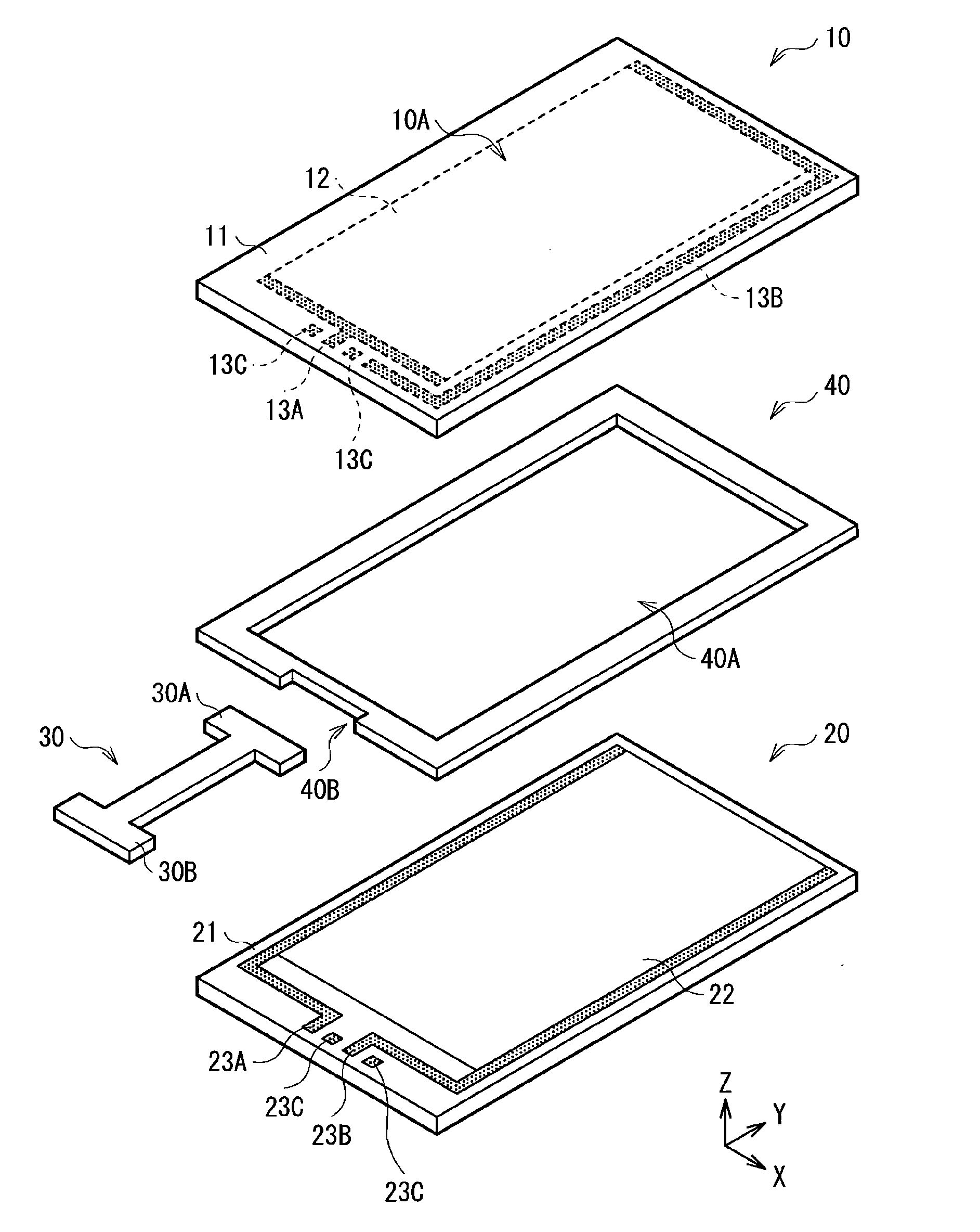
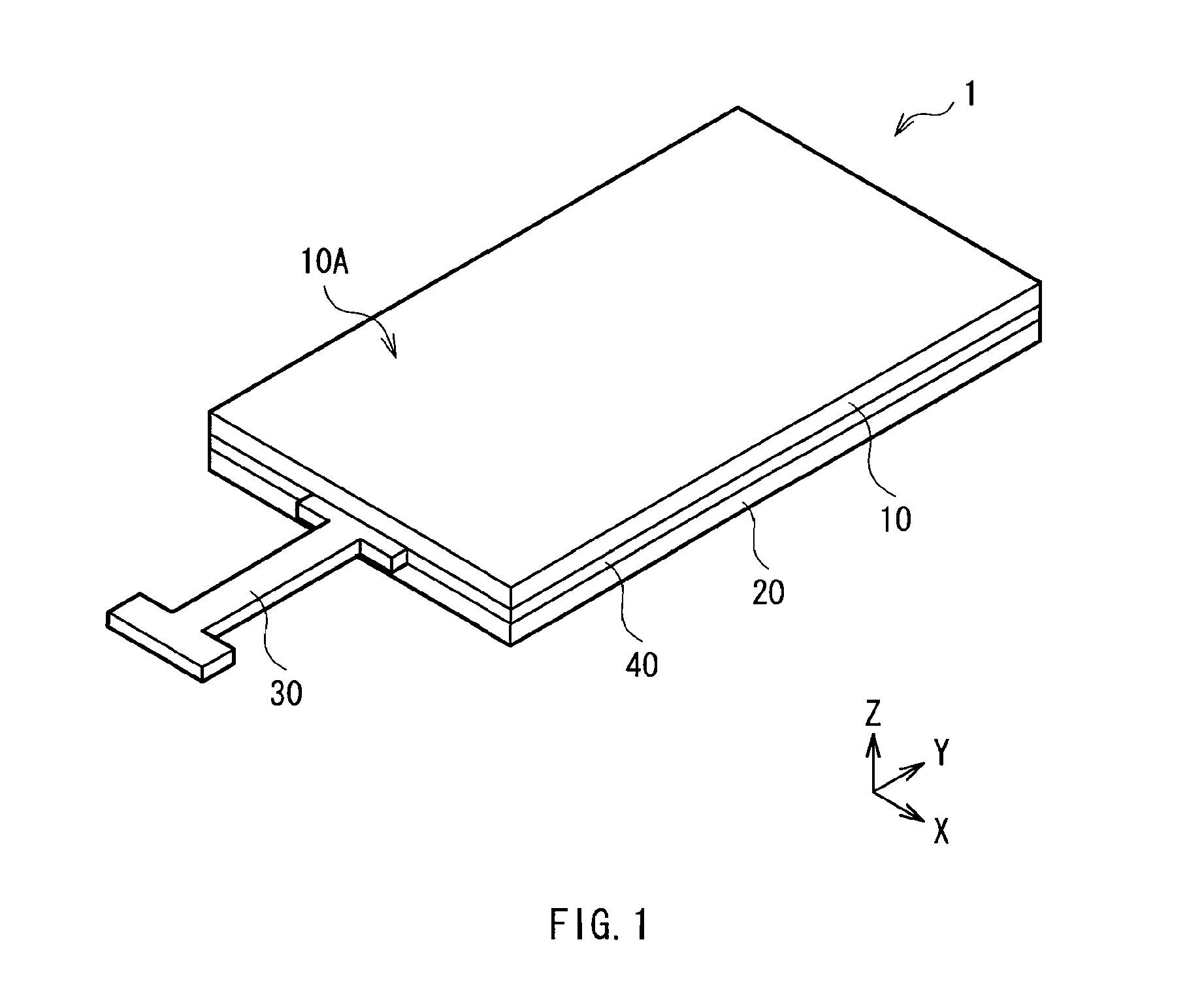
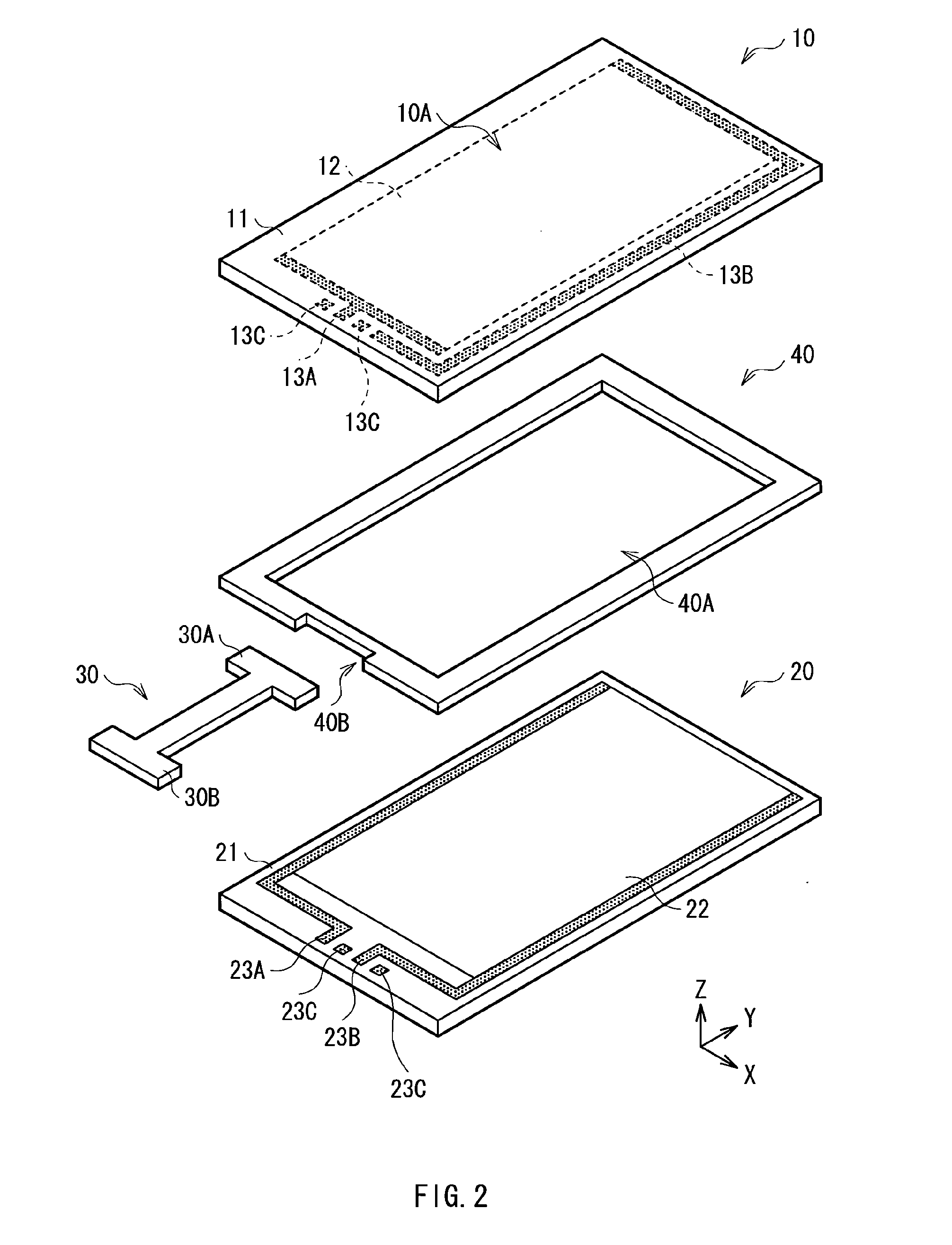
[0092]FIG. 1 illustrates a perspective view of a schematic configuration of a touch panel 1 according to a first embodiment of the invention. FIG. 2 illustrates an exploded view of the touch panel 1 in FIG. 1. The touch panel 1 according to the embodiment is laid over, for example, a display including a liquid crystal panel, an organic EL panel or the like to be used as a screen input display, and when a surface of the touch panel 1 is pressed with a finger, a pen or the like, selections for display on a display screen of the display is directly made. Kinds of touch panels include a resistive touch panel, a capacitive touch panel and the like. In the embodiment, the case where the present invention is applied to the resistive touch panel will be described as an example.

[0093]The touch panel 1 includes, for example, a pair of an upper substrate 10 and a lower substrate with a predetermined space in between. A flexible printed circuit (FPC) 30 and an adhesive layer 40 are arranged bet...

second embodiment

[0118]FIG. 15 illustrates an example of a sectional configuration of a touch panel 2 according to a second embodiment of the invention. The touch panel 2 according to the embodiment is distinguished from the touch panel 1 according to the first embodiment by the fact that the touch panel 2 includes a flexible printed circuit (FPC) 50 instead of the FPC 30. Therefore, features different from the first embodiment will be mainly described below, and features common to the first embodiment will not be described.

[0119]The sectional configuration illustrated in FIG. 15 corresponds to an end section 50A (a section corresponding to the end section 30A of the FPC 30) of the FPC 50 in the touch panel 2. FIG. 16 illustrates a surface view on a side close to the lower substrate 20 of the end section 50A, and FIG. 17 illustrates a surface view on a side close to the upper substrate 10 of the end section 50A. FIGS. 18, 19, 20 and 21 illustrate sectional views taken along lines A-A, B-B, C-C and D...

third embodiment

[0133]FIG. 25 illustrates an example of a sectional configuration of a touch panel 3 according to a third embodiment of the invention. The touch panel 3 according to the embodiment is distinguished from the touch panel 2 according to the second embodiment by the fact that the touch panel 3 includes a flexible printed circuit (FPC) 60 instead of the FPC 50 in the second embodiment. Therefore, features different from the second embodiment will be mainly described below, and features common to the second embodiment will not be described.

[0134]The sectional configuration illustrated in FIG. 25 corresponds to an end section 60A (a section corresponding to the end section 50A of the FPC 50) of the FPC 60 in the touch panel 3. FIG. 26 illustrates a surface view on a side close to the lower substrate 20 of the end section 60A, and FIG. 27 illustrates a surface view on a side close to the upper substrate 10 of the end section 60A. FIGS. 28, 29, 30 and 31 illustrate sectional views taken alon...


PUM


Abstract

A flexible printed circuit includes: a flexible substrate extending from a first end section to a second end section, and having an opening or a notch in proximity to the first end section; a first wiring layer extending from the first end section to the second end section so as to avoid the opening or the notch; a second wiring layer extending from the first end section to the second end section so as to block the opening or the notch; a first conductive member being formed opposed to the flexible substrate in relation to the first wiring layer and at least in proximity to the first end section in a region opposed to the first wiring layer, and being electrically connected to the first wiring layer; and a second conductive member electrically connected to the second wiring layer via the opening or the notch.

Description

BACKGROUND OF THE INVENTION[0001]1. Field of the Invention[0002]The present invention relates to a flexible printed circuit performing signal transmission from one device to another device, and a touch panel, a display panel and a display each of which includes the flexible printed circuit.[0003]2. Description of the Related Art[0004]Techniques of detecting a position touched by an object to be detected such as a finger or a pen on a display surface of a display have been heretofore known. Among them, a typical and widespread technique is a display including a touch panel. There are various types of touch panels, but a resistive touch panel is commonly used. In the resistive touch panel, a panel surface has a laminate configuration in which a very small spacer is sandwiched between glass and a film opposed to each other, and a transparent electrode grids are arranged on opposed surfaces of the glass and the film. Then, when a finger or a pen touches a surface of the film, the film i...

Claims


Application Information

Patent Timeline
Patent Type & Authority Applications(United States)
IPC IPC(8): G06F3/045H05K1/02
CPCH05K3/281H05K3/323H05K3/361H05K3/421H05K2201/0394H05K2203/1572H05K2201/09481H05K2201/09563H05K2201/097H05K2201/09781H05K2201/0979H05K2201/09472
Inventor OIKAWA, HARUTOSHIKIMURA, KIYOHIRO
Owner SONY CORP
Why Eureka
Try Eureka