Power supply abnormality detection circuit for on-vehicle electronic control device

a technology of abnormal state detection and electronic control device, which is applied in emergency protection of supplying operative power, testing electric installations on transport, transportation and packaging, etc., can solve the problems of inability to identify abnormalities, conventional technologies, and difficulty in determining and storing abnormal states in on-vehicle electronic control device without power being fed, etc., to improve contact reliability, improve maintainability, and reduce size

Active Publication Date: 2009-12-24
MITSUBISHI ELECTRIC CORP
View PDF3 Cites 35 Cited by
  • Summary
  • Abstract
  • Description
  • Claims
  • Application Information

AI Technical Summary

Benefits of technology

[0019]Therefore, even when contact failure occurs in the main power supply terminal, the on-vehicle electronic control device is fed with power. Thus, there is an effect that the on-vehicle electronic control device is prevented from generating an abnormal control output to ensure safety, and then one of a report of an abnormality occurrence state and a storage of at least abnormality occurrence history information for facilitating a maintenance check is performed, thereby improving maintainability.
[0020]The present invention is particularly effective when the number of main power supply terminals connected in parallel is small in a case where, for example, a plurality of ground terminals are connected in parallel to improve contact reliability because the number of terminals of the connector is tight. Therefore, there is an effect that the on-vehicle electronic control device can be reduced in size at low cost.

Problems solved by technology

However, for example, while the on-vehicle electronic control device is not fed with power because of the abnormality of the power supply relay, it is difficult to determine and store an abnormal state in the on-vehicle electronic control device with no power being fed.
However, the conventional technologies have the following problems.
However, when contact failure of a connector to be connected with an electrical device causes the abnormality regardless of the normal operation of a power supply relay (not shown), there is a problem in that the cause of the abnormality cannot be identified.
In addition, there is a problem in that the electrical device itself cannot determine the abnormality, report the abnormality, or store abnormality occurrence information.
The electronic control unit is generally housed in a sealed case including high-density contactless electronic parts, and thus electromagnetic relays which are consumable parts causing contact arc cannot be incorporated.
Therefore, when the contact failure of the connector to be connected with the electronic control unit causes the abnormality, there is a problem in that the cause of the abnormality cannot be identified.
In addition, there is a problem in that the electronic control unit itself cannot determine the abnormality, report the abnormality, or store the abnormality occurrence information.
However, the abnormality occurrence information cannot be stored.
In addition, there is a problem in that whether the output contact causes the contact failure or a power supply terminal of the connector causes the contact failure cannot be determined.
The back-up power supply device for a vehicular electronic control unit which is described in JP 08-198038 A requires power transistors serving as a back-up power supply, which may cause increases in size and cost.

Method used


Image

  • Power supply abnormality detection circuit for on-vehicle electronic control device
  • Power supply abnormality detection circuit for on-vehicle electronic control device
  • Power supply abnormality detection circuit for on-vehicle electronic control device

Examples


embodiment 1

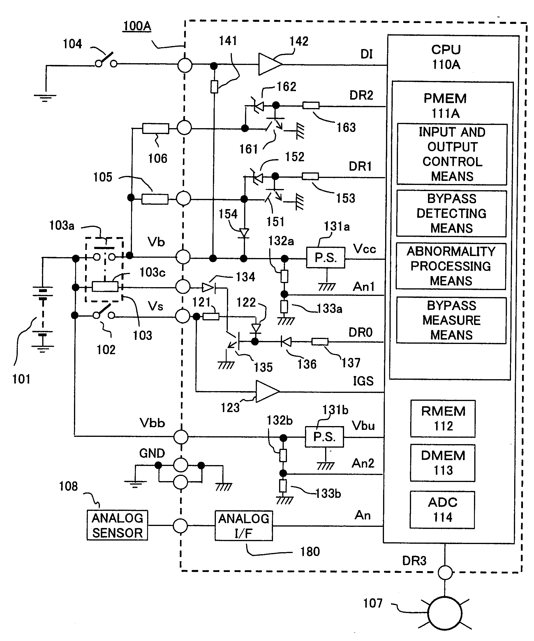
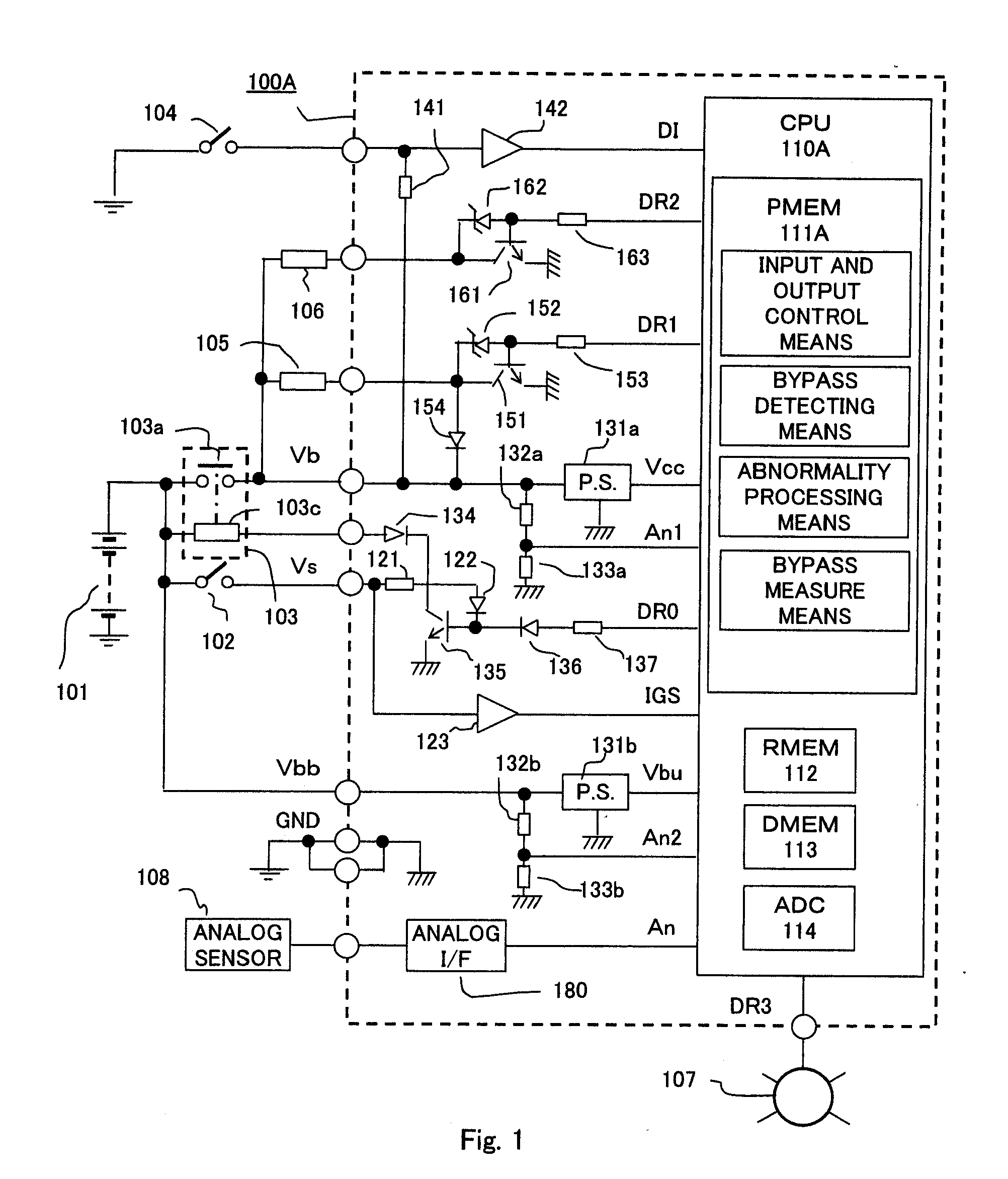
[0028]FIG. 1 is an entire structural diagram showing an on-vehicle electronic control device according to Embodiment 1 of the present invention. In FIG. 1, an on-vehicle electronic control device 100A includes a microprocessor 110A as a main part and is fed with power from an on-vehicle battery 101 through an output contact 103a of a power supply relay 103 and a main power supply terminal Vb of a connector (not shown).

[0029]The power supply relay 103 includes an exciting coil 103c energized in response to actuation of a power supply switch 102. The power supply switch 102 is connected with the on-vehicle electronic control device 100A through an instruction power supply terminal Vs.

[0030]An switching sensor 104 which is provided outside the on-vehicle electronic control device 100A and connected therewith represents, for example, a high-speed switching signal ON / OFF-operated in synchronization with rotation of an engine such as an engine rotation sensor or a crank angle sensor, or a...

embodiment 2

[0105]FIG. 3 is an entire structural diagram showing an on-vehicle electronic control device according to Embodiment 2 of the present invention. Points different from the structure of FIG. 1 according to Embodiment 1 will be mainly described below. Note that the reference symbols in each drawing indicate the same or corresponding portions.

[0106]In FIG. 3, an on-vehicle electronic control device 100B includes a microprocessor 110B as a main part. As in the case of FIG. 1, a power supply switch 102, a power supply relay 103, a switching sensor 104, a first electrical load 105, a second electrical load 106, a warning indicator 107, and an analog sensor 108 are provided outside the on-vehicle electronic control device 100B and connected with one another.

[0107]As in the case of FIG. 1, the on-vehicle electronic control device 100B includes a microprocessor 110B, a main power supply circuit 131a, an auxiliary power supply circuit 131b, an input interface circuits 142 and 180, a first swit...

embodiment 3

[0147]FIG. 5 is a partial structural diagram showing an on-vehicle electronic control device according to Embodiment 3 of the present invention. Points different from the structure of FIG. 3 according to Embodiment 2 will be mainly described below. Note that the reference symbols in each drawing indicate the same or corresponding portions. Further, the flowchart shown in FIG. 4, which has been used to describe Embodiment 2, will be used for convenience.

[0148]In FIG. 5, an on-vehicle electronic control device 100C includes a microprocessor 110C as a main part. A power supply relay 103 (not shown), a switching sensor 104, and an analog sensor 108 are provided outside the on-vehicle electronic control device 100C and connected with one another.

[0149]A plurality of first electrical loads 105a and 105b are, for example, a pair of variable valve timing controlling solenoids. A second electrical load 106a is a solenoid for driving an electromagnetic valve for fuel injection. A second elect...


PUM


Abstract

The on-vehicle electronic control device includes a main power supply circuit fed with power from an on-vehicle battery through an output contact of a power supply relay and a main power supply terminal of a connector to supply a stabilized control voltage to a microprocessor. When contact failure occurs in the main power supply terminal, the main power supply circuit is fed with bypass power from the output contact through a first electrical load and a commutation diode to perform the one of the report of the abnormality and the storage of the abnormality occurrence history information. A bypass power fed state is detected when an input voltage to the main power supply circuit is lower than a power supply voltage of the on-vehicle battery.

Description

BACKGROUND OF THE INVENTION[0001]1. Field of the Invention[0002]The present invention relates to a power supply abnormality detection circuit for an on-vehicle electronic control device, for reducing an abnormality of a feed circuit, and particularly, a trouble caused due to contact failure of a power supply terminal of a connector for connection in, for example, an engine control device fed with power from an on-vehicle battery through an output contact of a power supply relay.[0003]2. Description of the Related Art[0004]In an on-vehicle electronic control device fed with power from an on-vehicle battery through an output contact of a power supply relay, when an operation of the on-vehicle electronic control device is abnormal, it is important to determine whether or not a normal power supply voltage is applied in order to facilitate a maintenance check.[0005]However, for example, while the on-vehicle electronic control device is not fed with power because of the abnormality of the...

Claims


Application Information

Patent Timeline
Patent Type & Authority Applications(United States)
IPC IPC(8): H02H1/06
CPCG01R31/007B60R16/03
Inventor MAEDA, TETSUOYUHARA, MASAHARUFUJITA, MASAHIDETAKATA, MICHIHIROYANO, TAKAYUKIYASE, DAISUKE
Owner MITSUBISHI ELECTRIC CORP
Why Eureka
Try Eureka