Vehicle control device

a control device and vehicle technology, applied in the field of control devices, can solve the problems of difficult sequential generation of optimal reference state amounts, difficult to ideally control and hotness of the braking system, so as to reduce the operation of the actuator device, and enhance the robustness against disturbance factors or changes

Active Publication Date: 2009-12-24
HONDA MOTOR CO LTD
View PDF15 Cites 48 Cited by
  • Summary
  • Abstract
  • Description
  • Claims
  • Application Information

AI Technical Summary

Benefits of technology

[0019]According to the first invention, basically, the operation of an actuator device of the actual vehicle is feedback-controlled by the actual vehicle actuator operation control input so as to approximate the first state amount error to zero, and a vehicle motion on the vehicle model and eventually the first model state amount are manipulated by the model operation control input so as to approximate the first state amount error to zero. This arrangement prevents an actual vehicle motion and a vehicle motion on the vehicle model from becoming considerably apart from each other due to influences of disturbance factors or the like.
[0504]As is obvious from the above explanation, the present invention is usefully applied to allow motions of an automobile or a two-wheeled motor vehicle to be controlled to desired motions with high robustness.

Problems solved by technology

However, the technology disclosed in the above-mentioned patent document 1 has been presenting the following inconveniences.
Meanwhile, it is practically difficult to sequentially generate optimum reference state amounts while taking all disturbance factors into account by using a vehicle model or the like.
In such a case, an operation of a vehicle actuator is controlled on the basis of a control input that is unsuited to an actual vehicle behavior or the operation of the actuator is restricted by a limiter, thus making it difficult to ideally control the operation of the actuator.
Further, frequent use of a braking system of a vehicle by automatic control may cause the braking system (especially a brake pad, a brake disc or the like) to become hot.
As a result, however, a control system of the vehicle has been exhibiting a nonlinear characteristic, which inconveniently leads to deteriorated robustness of the vehicle control, as compared with the case where no dead zone is provided.

Method used


Image

  • Vehicle control device
  • Vehicle control device
  • Vehicle control device

Examples


first embodiment

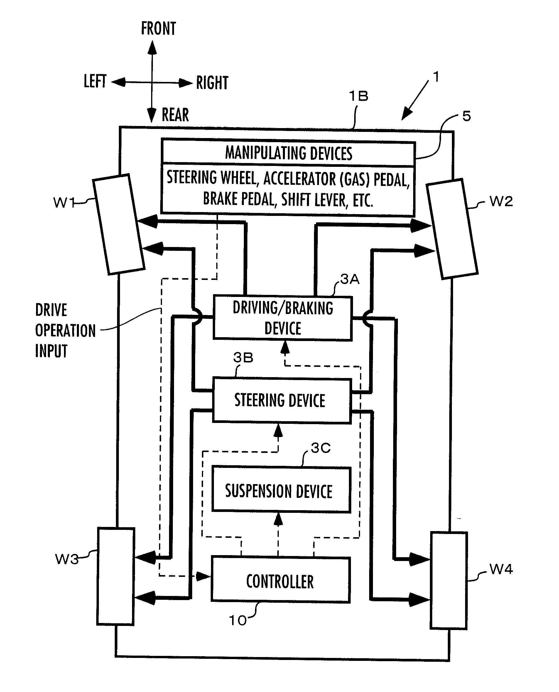
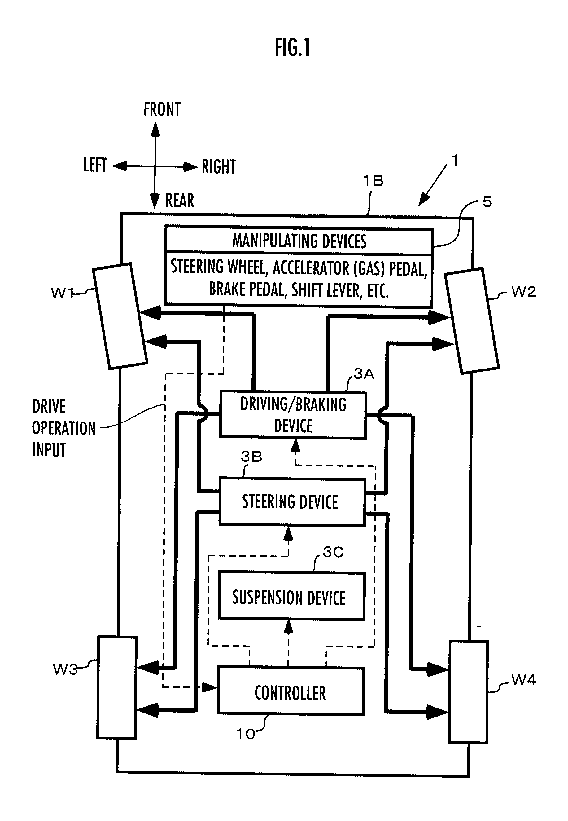
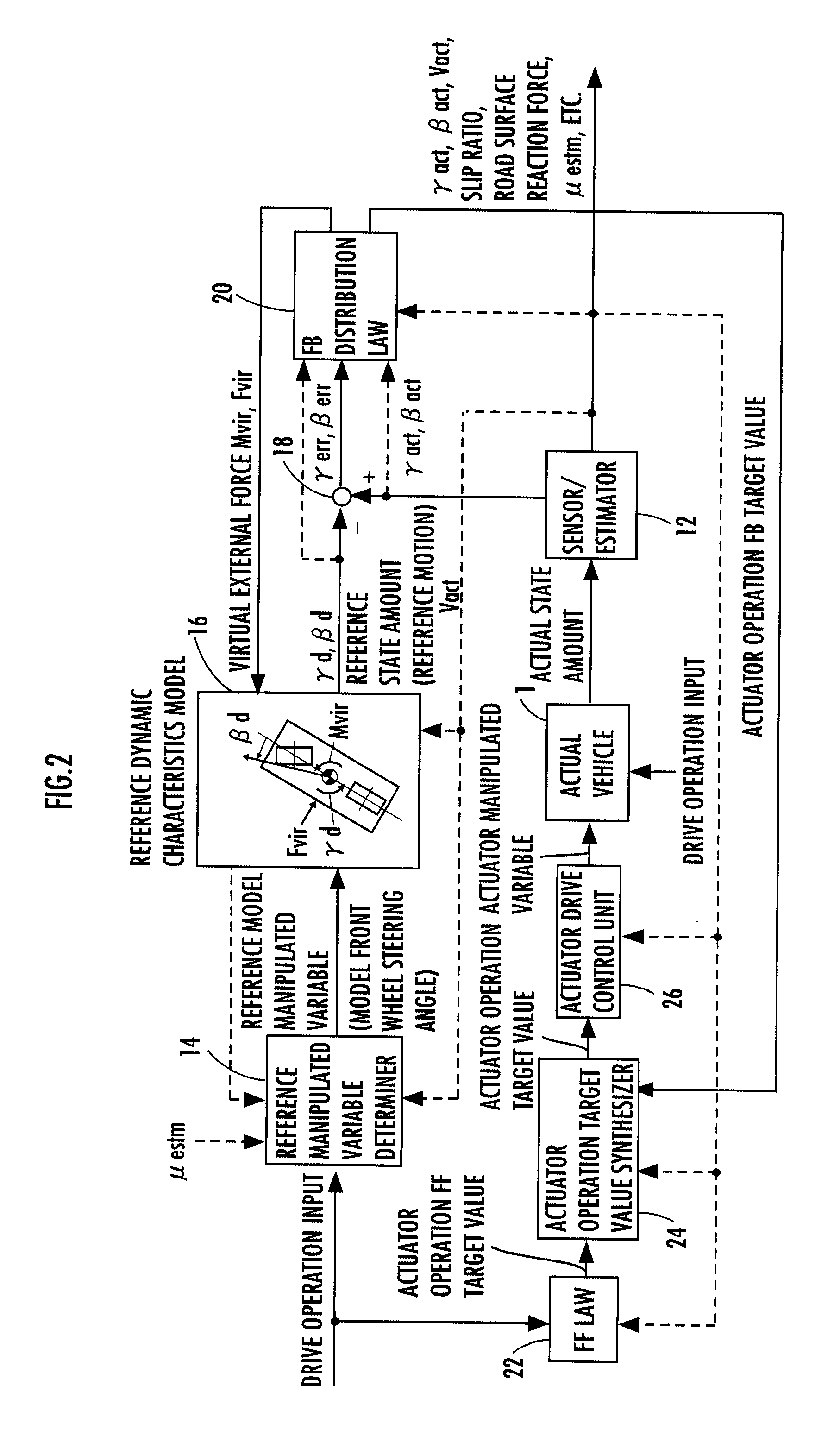
[0073]The control processing by a controller 10 in a first embodiment will now be schematically explained by referring to FIG. 2. FIG. 2 is a functional block diagram showing an overview of an entire control processing function of the controller 10. In the following explanation, a real vehicle 1 will be referred to as an actual vehicle 1.

[0074]The portion excluding the actual vehicle 1 in FIG. 2 (more precisely, the portion excluding the actual vehicle 1 and sensors included in a sensor / estimator 12, which will be discussed later) corresponds to the primary control processing function of the controller 10. The actual vehicle 1 in FIG. 2 is provided with the driving / braking device 3A, the steering device 3B, and the suspension device 3C described above.

[0075]As illustrated, the controller 10 is equipped with, as its main processing function components, the sensor / estimator 12, a reference manipulated variable determiner 14, a reference dynamic characteristics model 16, a subtracter 1...

second embodiment

[0382]A second embodiment of the present invention will now be explained with reference to FIG. 21. The present embodiment differs from the first embodiment described above only partly in processing, so that the explanation will be focused mainly on different aspects and the explanation of the same portions will be omitted. Further, in the explanation of the present embodiment, the same constituent portions or the same functional portions as those of the first embodiment will be assigned the same reference characters as those in the first embodiment.

[0383]According to a feedback control theory, basically, an actuator operation FB target value is ideally determined such that a feedback yaw moment basic required value Mfbdmd based on the state amount errors γerr and βerr is satisfied. However, in the aforesaid first embodiment, a moment in the yaw direction generated about the center-of-gravity point G of the actual vehicle 1 by an actuator operation FB target value incurs an excess o...

third embodiment

[0396]A third embodiment of the present invention will now be explained with reference to FIG. 22 to FIG. 24. The present embodiment differs from the aforesaid first embodiment only partly in processing, so that the explanation will be focused mainly on the different aspect, and the explanation of the same portions will be omitted. In the explanation of the present embodiment, the same constituent portions or the same functional portions as those of the first embodiment will be assigned the same reference characters as those of the first embodiment.

[0397]In the aforesaid first embodiment, as the actuator operation FB target value for the driving / braking device 3A, the aforesaid FB target n-th wheel brake driving / braking force Fxfbdmd_n, which means a correction required value (a correction required value for bringing the state amount errors γerr and βerr close to zero) of the driving / braking force to be applied to the n-th wheel Wn (n=1, 2, 3, 4) by an operation of the braking devic...


PUM


Abstract

An FB distribution rule 20 determines an actual vehicle actuator operation control input and a vehicle model operation control input such that a difference between a reference state amount determined by a vehicle model 16 and an actual state amount of an actual vehicle 1 (a state amount error) approximates to zero, and the control inputs are used to operate an actuator device 3 of the actual vehicle 1 and the vehicle model 16. In the FB distribution law 20, when an actual vehicle feedback required amount based on the state amount error exists in a dead zone, then an actual vehicle actuator operation control input is determined by using the required amount as a predetermined value. A vehicle model manipulated variable control input is determined such that a state amount error is brought close to zero, independently of whether an actual vehicle feedback required amount exists in a dead zone. This enhances linearity of a control system and also enhances the robustness against disturbance factors or changes therein while carrying out operation control of an actuator that suits a behavior of an actual vehicle as much as possible.

Description

TECHNICAL FIELD [0001]The present invention relates to a control device for a vehicle having a plurality of wheels, such as an automobile (engine automobile), a hybrid car, and a two-wheeled motor vehicle.BACKGROUND ART[0002]A vehicle, such as an automobile, is provided with systems, including a driving / braking system that transmits a driving force from a propulsive force generating source, such as an engine, to wheels or imparts a braking force, a steering system (steering control system) for controlling the steering control wheels of a vehicle, and a suspension system that elastically supports a vehicle body on wheels, as main mechanisms. Furthermore, in recent years, there has been known a vehicle provided with a variety of electric or hydraulic actuators to actively (positively) control the operations of the actuators according to a traveling condition of the vehicle or an environmental condition or the like rather than merely passively operating the systems in response to opera...

Claims


Application Information

Patent Timeline
Patent Type & Authority Applications(United States)
IPC IPC(8): B60W30/02B60W10/04B60W10/10B60W10/18B60W10/20B60T8/174B60T8/1755B60W10/00B60W10/06B60W10/08B60W10/12B60W10/184B60W10/22B60W30/00B60W50/06B62D6/00B62D101/00B62D137/00
CPCB60T8/1755B60T2270/86B60W10/04B60W10/10B60W10/18B62D6/003B60W2050/0028B60W2050/0033B60W2050/0034B60Y2200/12B60W50/06B60W30/02B60W40/10B60W30/18
Inventor TAKENAKA, TORUTOYOSHIMA, TAKAYUKIURABE, HIROYUKIKONO, HIROSHI
Owner HONDA MOTOR CO LTD
Why Eureka
Try Eureka