
Decoupling dynamic program analysis from execution across heterogeneous systems

Active Publication Date: 2009-12-24
VMWARE INC
View PDF5 Cites 29 Cited by
  • Summary
  • Abstract
  • Description
  • Claims
  • Application Information

AI Technical Summary

Benefits of technology

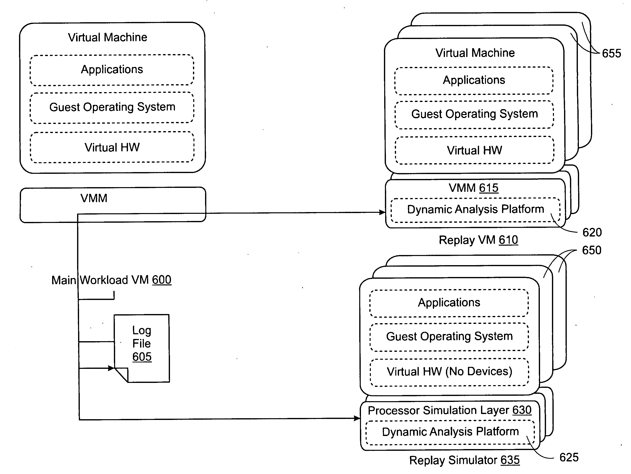
[0006]In another embodiment, a replay platform is placed between a recording platform and an analysis platform to lessen the burden on the recording platform. A method for analyzing a computer program according to this embodiment comprises the steps of recording a log comprising non-deterministic inputs to devices of a main workload virtual machine, replaying an execution behavior of the main workload virtual machine at a replay virtual machine using the log comprising non-deterministic inputs, recording a log comprising data outputs of devices of the replay virtual machine, replaying an execution behavior of the replay virtual machine on an analysis platform, and executing program analysis on the analysis platform during replay of the execution behavior of the replay virtual machine.

Problems solved by technology

Dynamic program analysis adds overhead to the execution of the computer program because it is executed “inline” with program execution.
Some dynamic program analysis (e.g., instrumentation and probing functionality, etc.) can add sufficient overhead to the execution of the program to perturb the processor workload and even cause “heisenbugs,” i.e., where the phenomenon under observation is changed or lost due to the measurement itself.
For example, dynamic program analysis commonly used for detecting buffer overflow or use of undefined memory routinely incurs overhead on the order of 10-40×, rendering many production workloads unusable.
Even in nonproduction settings, such as program development or quality assurance, this overhead may dissuade use in longer more realistic tests.
As such, to minimize performance costs, dynamic program analysis tools today perform a minimal set of checks, meaning that many critical software flaws can remain overlooked.

Method used


Image

  • Decoupling dynamic program analysis from execution across heterogeneous systems
  • Decoupling dynamic program analysis from execution across heterogeneous systems
  • Decoupling dynamic program analysis from execution across heterogeneous systems

Examples


Embodiment Construction

A. Virtualization Platform Architecture

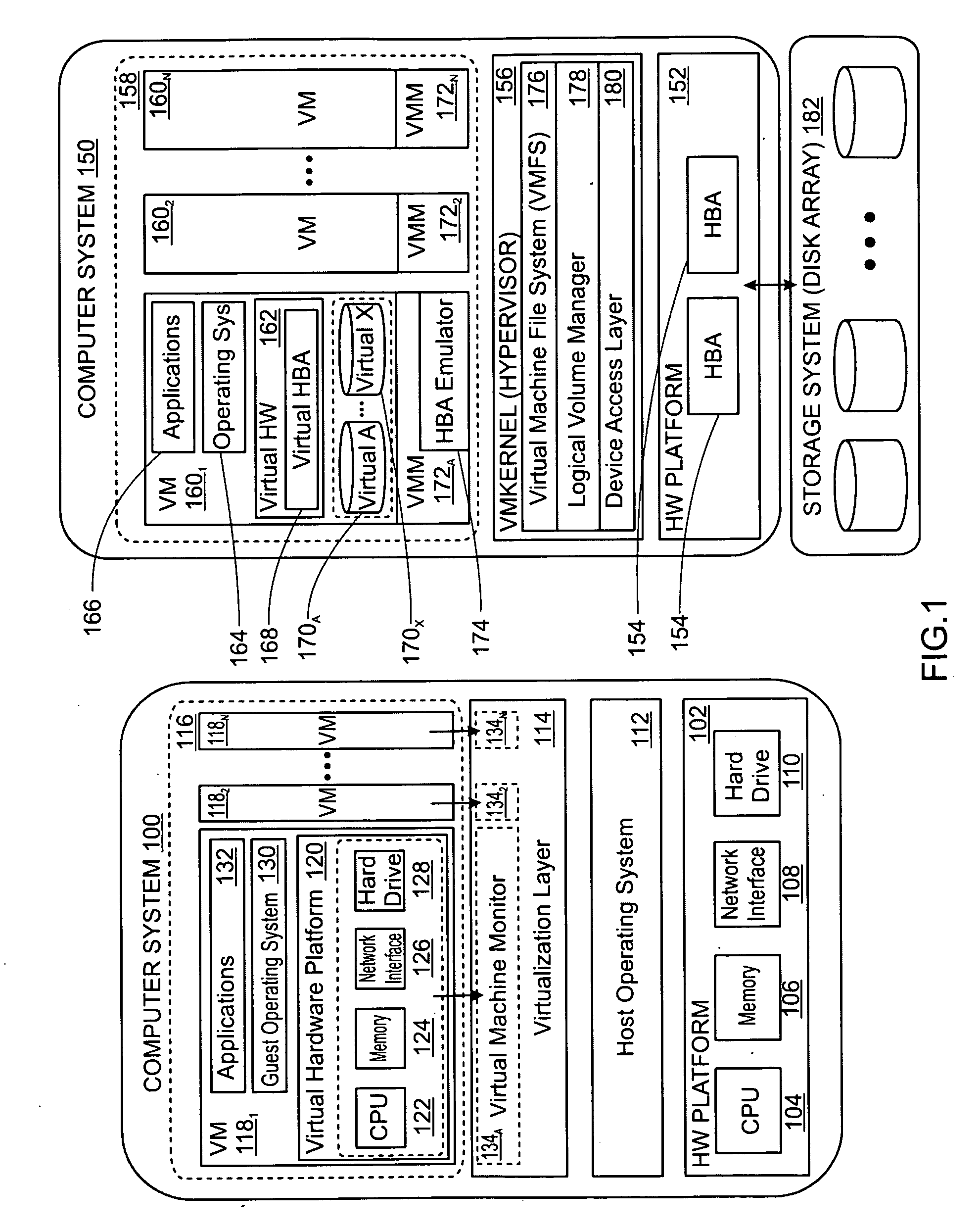
[0019]FIG. 1 depicts functional block diagrams of virtualized computer systems in which one or more embodiments of the invention may be practiced. Computer system 100 may be constructed on a typical desktop or laptop hardware platform 102 such as an x86 architecture platform. Such a hardware plaform may include CPU 104, RAM 106, network card 108, hard drive 110 and other I / O devices such as a mouse and a keyboard (not shown in FIG. 1). Host operating system 112 such as Microsoft Windows, Linux or NetWare runs on top of hardware platform 102. Virtualization software layer 114 is installed on top of host operating system 112 and provides a virtual machine execution space 116 within which multiple virtual machines (VMs) 1181-118N may be concurrently instantiated and executed. In particular, virtualization layer 114 maps physical resources of hardware platform 102 (e.g., CPU 104, RAM 106, network card 108, hard drive 110, mouse, keyboard, etc.) to ...


PUM


Abstract

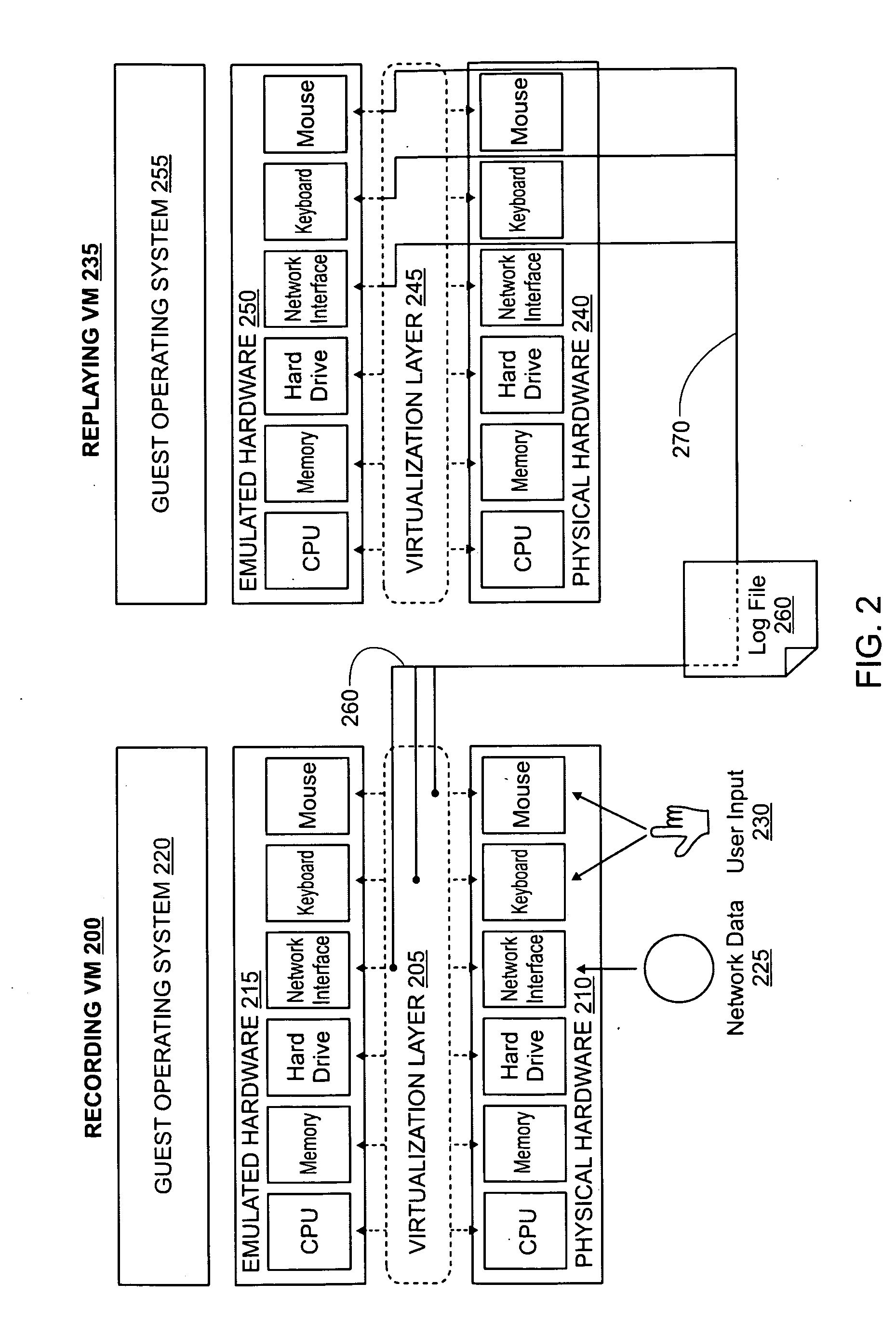
Dynamic program analysis is decoupled from execution in virtual computer environments so that program analysis can be performed on a running computer program without affecting or perturbing the workload of the system on which the program is executing. Decoupled dynamic program analysis is enabled by separating execution and analysis into two tasks: (1) recording, where system execution is recorded with minimal interference, and (2) analysis, where the execution is replayed and analyzed. Recording and analysis are carried out on heterogeneous systems so that they can be separately optimized.

Description

CROSS-REFERENCE TO RELATED APPLICATIONS[0001]The present application claims the benefit of U.S. provisional patent application Ser. No. 60 / 074,236, filed on Jun. 20, 2008, and entitled “Decoupling Dynamic Program Analysis From Execution In Virtual Environments,” which is hereby incorporated by reference. The present application also incorporates by reference the following: U.S. patent application entitled “Decoupling Dynamic Program Analysis From Execution In Virtual Environments” and filed on Sep. 26, 2008 (Attorney Docket No.: A242), U.S. patent application entitled “Synchronous Decoupled Program Analysis In Virtual Environments” and filed on Sep. 26, 2008 (Attorney Docket No.: A270), and U.S. patent application entitled “Accelerating Replayed Program Execution To Support Decoupled Program Analysis” and filed on Sep. 26, 2008 (Attorney Docket No.: A271).BACKGROUND OF THE INVENTION[0002]Dynamic program analysis involves the analysis of a computer program while it is executing in re...

Claims


Application Information

Patent Timeline
IPC IPC(8): G06F9/455G06F9/45
CPCG06F11/3612G06F2009/45591G06F9/45558G06F11/3636
Inventor CHOW, JAMESGARFINKEL, TALCHEN, PETER M.
Owner VMWARE INC
Learn More