Secondary drive axle disconnect for a motor vehicle
Inactive Publication Date: 2009-12-31
CHRYSLER GROUP LLC
5 Cites 11 Cited by
AI-Extracted Technical Summary
Problems solved by technology
Secondary driveline components introduce additional mass, inertia and friction to the: drivetrain, which in turn translates to increased fuel consumption.
The secondary axle road wheels, however, will still be “back-driving” the secondary axle differential through the axle-shafts, and the res...
Method used
[0020]Second clutch assembly 100 (shown in FIG. 5) includes casing 102, which can be made from aluminum, or from another similarly high strength and temperature resistant material. Generally, aluminum is a preferred casing material for reasons of economy and weight. Casing 102 houses generally annular piston 150 slidably engaged with shaft 50A. Second clutch assembly 100 also includes generally annular friction plates 110 and reaction plates 130. Friction plates 110 and reaction plates 130 are arranged in alternating order, sandwiched between piston 150 and reaction surface 120A of retainer 120. Friction plates 110 have external diameter splines (not shown) which are used to engage retainer 120 via complementary splines on the retainer's internal diameter (not shown). Reaction plates 130 have internal diameter splines (not shown) which are used to engage sleeve 140 via complementary splines on the sleeve's external diameter (not shown). Retainer 120 is mechanically engaged with drive wheel 20B via shaft 50B, and sleeve 140 is mechanically engaged with differential 60 via shaft 50A.
[0022]Friction plates 110 and reaction plates 130 can be formed from any rigid, temperature resistant material, such as steel, with specially formulated fiction material bonded to both sides of each friction plate (not shown). Generally, steel is a preferred plate material for reasons of strength at elevated temperatures. The friction material has specific friction characteristics which allow friction plates 110 to slip relative to adjacent surfaces without damage as they are moved into contact and until they are fully clamped. In wet-type clutches, the working fluid is primarily adapted to enhance the clutch plates' friction coefficient and to remove excess heat generated by the slipping friction plates. Ability of the friction plates ...
Benefits of technology
[0006]The present invention is a drive disconnect system for a drivetrain of a motor vehicle of the type having either four-wheel or all-wheel drive capability. The active drive disconnect system is an active system, meaning that it can be operated while the vehicle is in motion. The system includes a drivetrain having a primary driveline and a secondary driveline, wherein the primary driveline has a primary axle arranged to drive the vehicle, and the secondary driveline has a secondary axle, a differential and two axle half-shafts arranged for selective mechanical engagement with the primary axle. The system also includes an active drive disconnect which has a first clutch assembly arranged between the primary driveline and the secondary driveline for engaging the corr...
Abstract
An active drive disconnect system for a drivetrain of a motor vehicle controlling selective engagement of a first clutch and a second clutch while the vehicle is in motion without the need for synchronization. In the active drive disconnect the first clutch assembly is arranged for selective engagement of a secondary driveline with a primary driveline, and the second clutch is arranged for selectively connecting an axle half-shaft with a differential.
Application Domain
Fluid couplingsMechanical actuated clutches +5
Technology Topic
ClutchDrivetrain +4
Image
Examples
- Experimental program(1)
Example
[0015]In general the present invention is directed to a drivetrain in a motor vehicle of the type having either four-wheel or all-wheel drive capability, and, more particularly, to a system for actively engaging the secondary drive axle in such a vehicle drivetrain without the need for synchronizing the disconnect. The term “disconnect”, as employed in the designation of the subject system, is used herein to describe both an engagement and a disengagement function performed in the vehicle drivetrain. The term “active” as employed herein denotes system function which is capable of being performed automatically, without operator control.
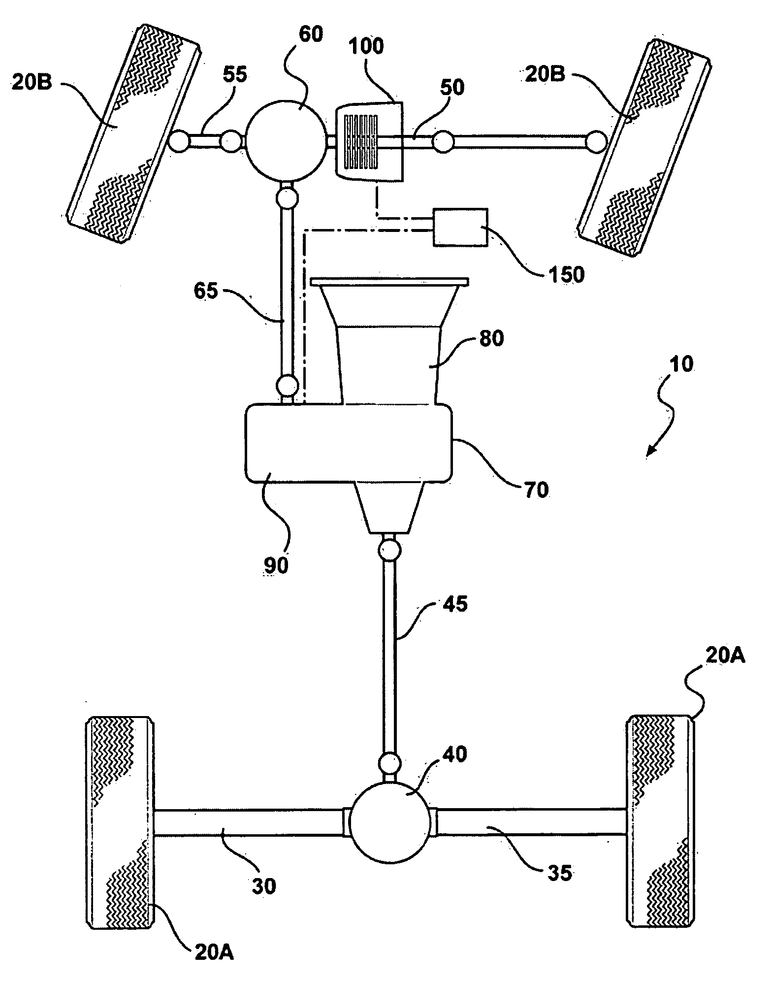
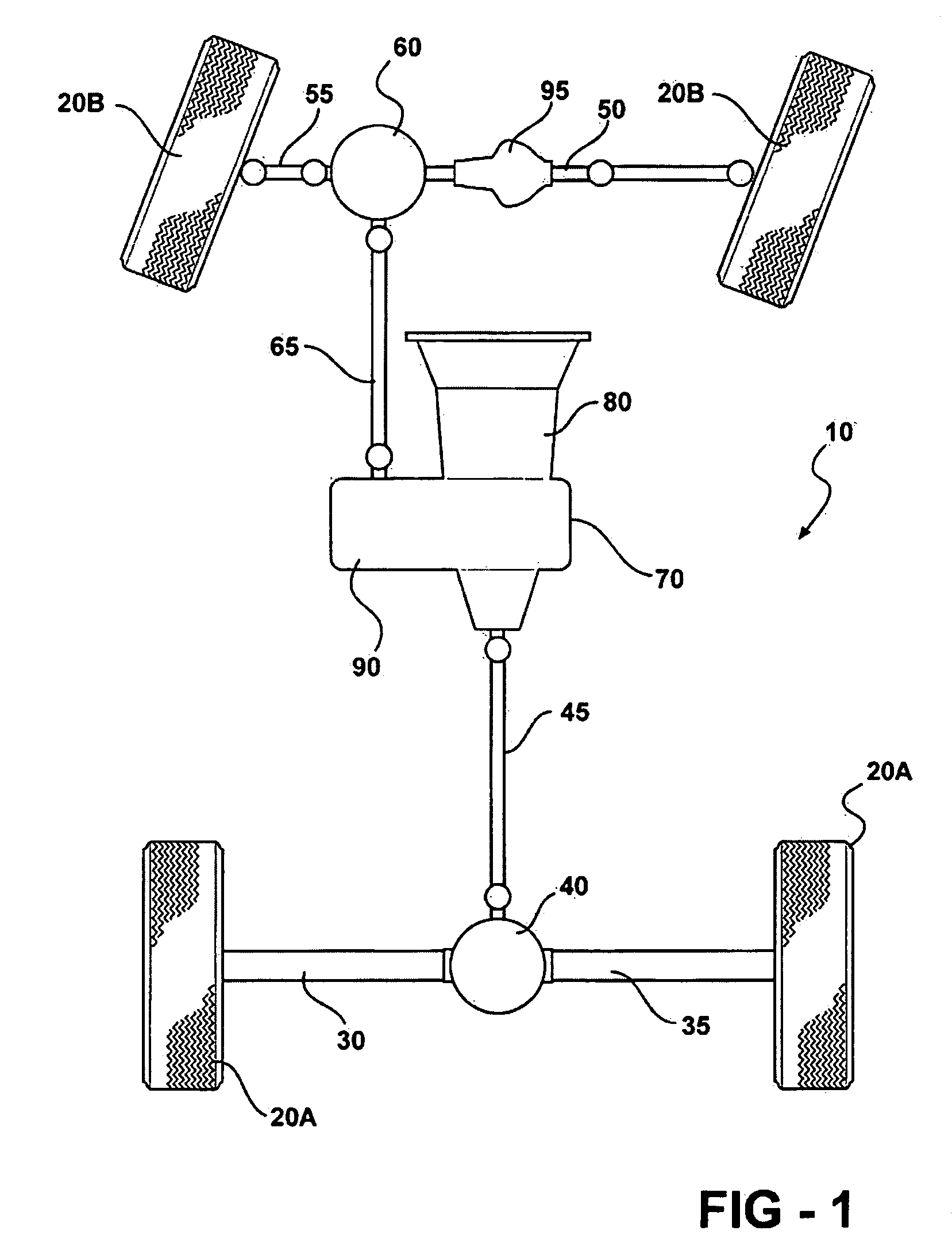
[0016]Referring now to the drawings in which like elements of the invention are identified with identical reference numerals throughout, FIG. 1 is a schematic diagram of a four-wheel or all-wheel drive drivetrain 10 of a motor vehicle having a primary driveline and a secondary driveline according to prior art. The primary driveline comprises a pair of drive wheels 20A connected to a primary axle which includes axle half-shafts 30 and 35 connected to differential 40, and prop-shaft 45 connected to transmission 80. The secondary driveline comprises a pair of drive wheels 20B, a secondary axle comprising axle half-shafts 50 and 55 connected at one end to drive wheels 20B and at their other end to differential 60. Prop-shaft 65 connects differential 60 to transfer case 70. Transfer case 70 is mounted to transmission 80 whereby it can function to selectively connect the secondary driveline to the primary driveline via engagement of clutch assembly 90.
[0017]According to prior art, axle half-shaft 50 may also include a secondary axle disconnect via dog-clutch 95 to interrupt torque transmission from one of the secondary driveline drive wheels to differential 60, i.e. eliminate back-driving of the differential. FIG. 2 denotes a cross-sectional view of a secondary axle disconnect via dog clutch 95 according to prior art. Dog-clutch 95 may be used together with clutch assembly 90 to disconnect the secondary driveline from the primary driveline and also eliminate back-driving of differential 60. While it may be possible to disengage dog-clutch 95 without it being synchronized with clutch assembly 90 when the vehicle is on the move, the dog-clutch may only be reengaged without synchronization when the vehicle is stopped. Consequently, there are no available means in the prior art drivetrain for reconnection of the secondary driveline to the primary driveline without synchronization of the clutch assembly and the dog-clutch.
[0018]FIG. 3 is a schematic diagram of an active drive disconnect system for a four-wheel or an all-wheel drivetrain 10 according to the invention. The active drive disconnect system comprises a first clutch assembly 90 which is mounted between the primary driveline and the secondary driveline. As shown in FIG. 3, the first clutch assembly is located within the transfer case 70. First clutch assembly 90 is arranged for selective engagement of the two drivelines. The active drive disconnect also includes second clutch assembly 100 which interrupts secondary axle half-shaft 50. Second clutch assembly 100 may be configured to run dry, or it may be immersed in a specially formulated working fluid of the type used in limited slip differentials or automatic transmissions, i.e. it can be a wet-type clutch.
[0019]Two variants of second clutch assembly are shown in FIGS. 4-6. FIG. 4 denotes a cross-sectional side view of the secondary driveline and axle-shaft 50A and axle-shaft 50B engaged via an electrically actuated second clutch assembly 100FIG. 5 shows a cross-sectional side view of an electrically actuated second clutch assembly 100, while FIG. 6 shows a cross-sectional side view of a hydraulically actuated second clutch assembly 100′. FIG. 5 shows an electrically actuated second clutch assembly 100 in an engaged state, wherein clutch friction plates 110 and 130 are clamped by a force being applied to slidably moveable clutch piston 150 in the direction of clutch retainer 120. FIG. 6 shows a hydraulically actuated second clutch assembly 100′ in a disengaged state, wherein there is no contact between clutch friction plates 110 and 130, and no friction plate contact with retainer 120 due to no force being applied to clutch piston 150′.
[0020]Second clutch assembly 100 (shown in FIG. 5) includes casing 102, which can be made from aluminum, or from another similarly high strength and temperature resistant material. Generally, aluminum is a preferred casing material for reasons of economy and weight. Casing 102 houses generally annular piston 150 slidably engaged with shaft 50A. Second clutch assembly 100 also includes generally annular friction plates 110 and reaction plates 130. Friction plates 110 and reaction plates 130 are arranged in alternating order, sandwiched between piston 150 and reaction surface 120A of retainer 120. Friction plates 110 have external diameter splines (not shown) which are used to engage retainer 120 via complementary splines on the retainer's internal diameter (not shown). Reaction plates 130 have internal diameter splines (not shown) which are used to engage sleeve 140 via complementary splines on the sleeve's external diameter (not shown). Retainer 120 is mechanically engaged with drive wheel 20B via shaft 50B, and sleeve 140 is mechanically engaged with differential 60 via shaft 50A.
[0021]Second clutch 100 is engaged, i.e. friction plates 110 and reaction plates 130 are clamped between reaction surface 120A and piston 150, by a force being applied on piston 150 urging friction plates 110 against reaction plates 130 and toward retainer 120. Shafts 50A and 50B are engaged, and a torque transfer chain is thereby created, when friction plates 110 and reaction plates 130 are clamped between piston 150 and retainer 120. For a hydraulically actuated second clutch assembly 100′ (shown in FIG. 6), piston 150′ is actuated, i.e. a force is applied, by a pressurized fluid supplied by pump 155 to pressure chamber 105. With respect to arrangement and function of friction plates 110, reaction plates 130 and reaction surface 120, second clutch assembly 100′ is identical to second clutch assembly 100. A force applied on piston 150′ urges friction plates 110 against reaction plates 130 and toward retainer 120 to engage shafts 50A and 50B.
[0022]Friction plates 110 and reaction plates 130 can be formed from any rigid, temperature resistant material, such as steel, with specially formulated fiction material bonded to both sides of each friction plate (not shown). Generally, steel is a preferred plate material for reasons of strength at elevated temperatures. The friction material has specific friction characteristics which allow friction plates 110 to slip relative to adjacent surfaces without damage as they are moved into contact and until they are fully clamped. In wet-type clutches, the working fluid is primarily adapted to enhance the clutch plates' friction coefficient and to remove excess heat generated by the slipping friction plates. Ability of the friction plates to slip without damage during engagement permits the second clutch assembly to absorb some difference in relative rotating speed between half-shaft 50 and prop-shaft 65 until the speed of one of the two shafts catches up to the other. This ability to absorb speed differences between the half-shaft and prop-shaft further allows first clutch 90 and second clutch assembly 100 (or second clutch assembly 100′) to be engaged smoothly at any vehicle road speed without the need for synchronization.
[0023]Electric motor 160, such as a direct current (DC) motor, in mechanical communication with piston 150, e.g. through a lever arrangement (not shown), or fluid pump 155 in fluid communication with piston 150′ may be employed to apply a desired force to the piston to engage the second clutch assembly. A fluid pump positioned externally (not shown) with respect to the second clutch assembly may be used in place of pump 155. Electric motor 160 or an external fluid pump can be mounted on the vehicle, in close proximity to the second clutch assembly. Electric motor 160, internal pump 155 or an external fluid pump may be actuated by an operator controlled switch located inside the passenger compartment of the vehicle, e.g. on the instrument panel (not shown), or automatically via an Electronic Control Unit (ECU).
[0024]Electric motor 160, internal fluid pump 155 an external fluid pump may be automatically actuated by an ECU in response to a signal detecting any one or more predetermined vehicle operating parameters that correspond to threshold loss of traction by the drive wheels. Generally, a particular minimum difference in rotational speed of the drive wheels will signify a threshold traction loss. Such minimum wheel speed difference may be predetermined, i.e. established empirically during the vehicle development phase under controlled conditions at an instrumented test-facility. For example, a development vehicle is run on various driving surfaces and the optimal point of actuation of the electric motor or the fluid pump for acceptable vehicle performance is identified and noted.
[0025]Sensors positioned in the vehicle at the individual wheels detect-wheel speeds. The wheel speed signals are communicated to a processor for comparison against the predetermined minimum wheel speed difference. The processor, generally incorporated into the ECU, calculates an actual wheel speed difference and compares it against the predetermined minimum value. The ECU issues a command to energize both first clutch 90 and second clutch assembly 100 (or second clutch assembly 100′) to engage the primary and the secondary drivelines when the actual wheel speed difference is greater than or equal to the predetermined minimum.
[0026]The active drive disconnect system may be employed in a hybrid-electric vehicle (HEV), i.e. a vehicle powered by a combination of an internal-combustion engine and a battery powered electric motor, equipped with a regenerative braking system. Typically, an HEV regenerative braking system employs a vehicle mounted generator that is arranged to be driven by the vehicle's drivetrain to recharge the accumulator when the braking system is applied to slow the vehicle. Generally, the amount of recharging power is directly proportional to braking energy dissipated at the wheels. In most vehicles front brakes provide a majority of braking power due to better traction at the front wheels, as well as for enhanced vehicle stability. Hence, especially in vehicles with the secondary driveline arranged in the front of the vehicle, drive wheels 20B must back-drive differential 60 to transfer the braking energy for driving the generator. Additionally, in order to obtain full recharging benefit of the vehicle's braking power, the primary and the secondary drivelines must be engaged when the brakes are applied. In such an HEV application, in addition to a fuel economy benefit, the present invention would facilitate regenerative braking by providing an active, seamless, non-synchronized engagement of the primary and the secondary drivelines.
[0027]The description of the invention is merely exemplary in nature and, thus, variations that do not depart from the gist of the invention are intended to be within the scope of the invention. Such variations are not to be regarded as a departure from the spirit and scope of the invention.
PUM


Description & Claims & Application Information
We can also present the details of the Description, Claims and Application information to help users get a comprehensive understanding of the technical details of the patent, such as background art, summary of invention, brief description of drawings, description of embodiments, and other original content. On the other hand, users can also determine the specific scope of protection of the technology through the list of claims; as well as understand the changes in the life cycle of the technology with the presentation of the patent timeline. Login to view more.