Fuel filter device

Active Publication Date: 2009-12-31
NIFCO INC
View PDF69 Cites 14 Cited by
  • Summary
  • Abstract
  • Description
  • Claims
  • Application Information

AI Technical Summary

Benefits of technology

[0005]The main problem which this invention attempts to solve is to make it possible to constitute a bag-like filter body easily and adequately while acc

Problems solved by technology

However, considering the manufacturing cost, and the like, of the filter body, there is a limit to the number of filter materials overlaid.
Also, because the number of filter materials at the plac

Method used


Image

  • Fuel filter device
  • Fuel filter device
  • Fuel filter device

Examples


Embodiment Construction

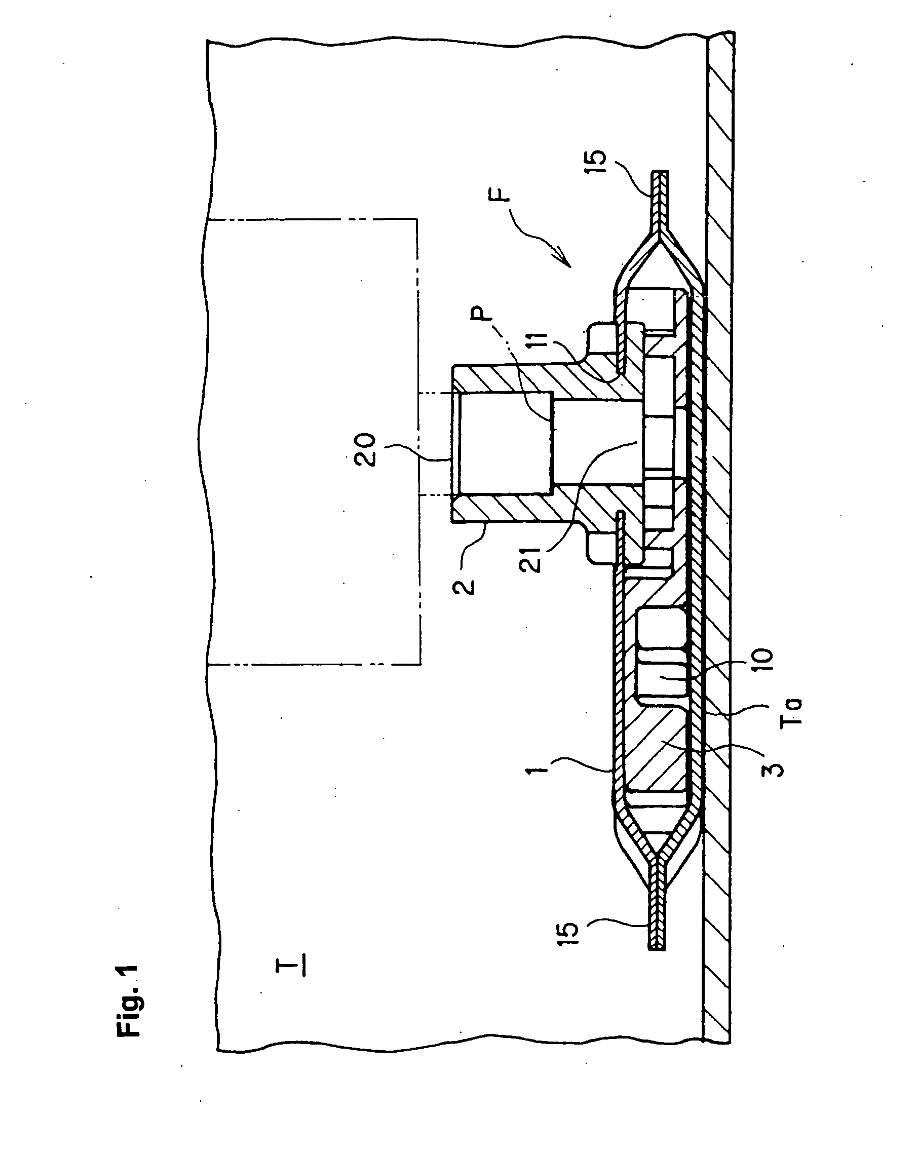
[0020]A preferred mode of working of this invention is explained below based on FIG. 1 and FIG. 2.

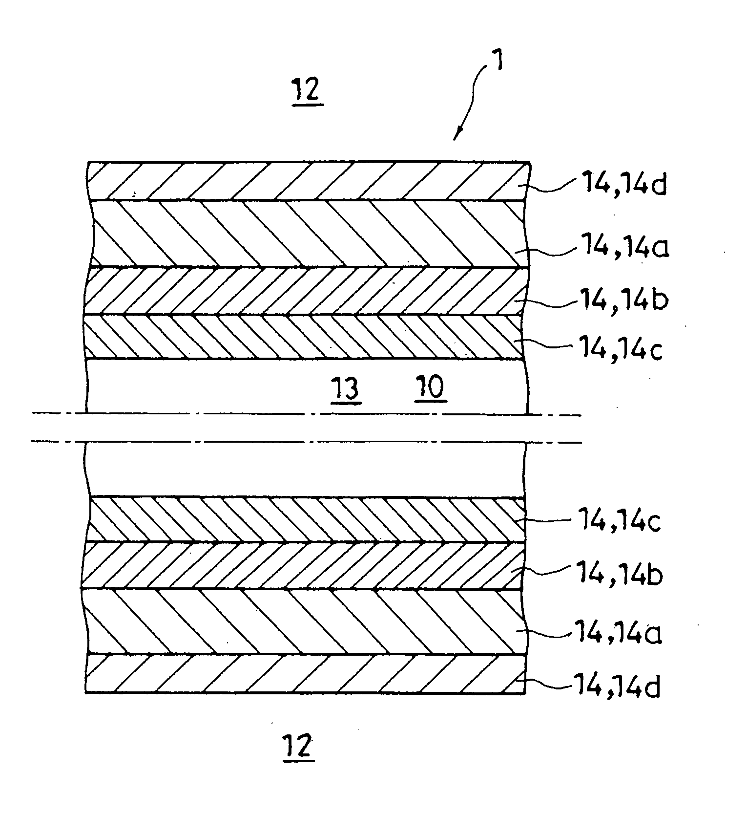
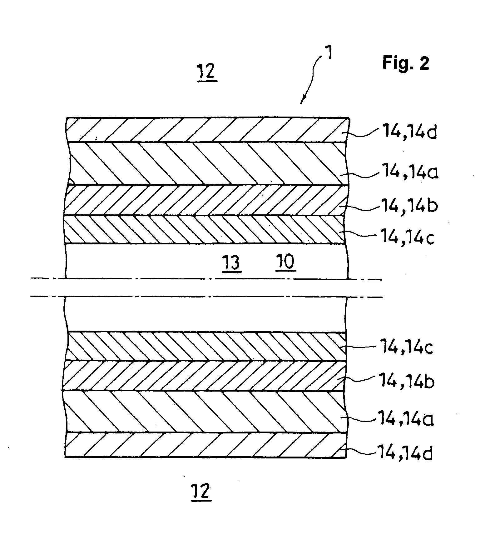
[0021]Here, FIG. 1 is a structural view showing the condition in which the filter device F is attached to the fuel intake port P inside the fuel tank T; also, FIG. 2 shows one example of the cross sectional structure of the filter body 1 constituting such filter device F. (In FIG. 2, only the cross sectional structure on the upper side and the lower side of the filter body 1 is represented, and the space forming member 3 held inside the filter body 1 is omitted.)

[0022]The fuel filter device F pertaining to this mode of working is attached to the fuel intake port P inside the fuel tank T of an automobile or motorcycle, or the like, so that water and foreign matter do not exit in the fuel sent to the internal combustion engine via such fuel intake port P.

[0023]Typically, such filter device F is attached to the fuel intake port P on an intake pipe having this fuel intake port P inside the ...


PUM

PropertyMeasurementUnit
Sizeaaaaaaaaaa
Areaaaaaaaaaaa
Particle sizeaaaaaaaaaa

Abstract

A filter device includes a bag-shape filter body. The filter device is attached in a manner such that an internal space of the filter body connects through to a fuel intake port in a fuel tank. The filter body includes two or more filter materials overlaying each other. At least one of the filter materials is configured so that a cross sectional area of its fuel passage is different between a primary side and a secondary side of the filter material so as to be a multifunctional filter material having a function of gradually capturing dust having different particle sizes.

Description

FIELD OF TECHNOLOGY[0001]This invention relates to an improvement of a fuel filter device to be attached to a fuel intake port in a fuel tank.BACKGROUND ART[0002]Fuel inside the fuel tank is sent to a side of the internal combustion engine through an intake pipe, and the like, disposed inside this fuel tank. A filter device is attached to the fuel intake port of such intake pipe in order to remove water from the fuel thus sent and to make it such that dust is not sent into the fuel pump. As such a filter device, there is one shown in Patent Document 1 disclosed by the present applicant.[0003]Inside the filter device of Patent Document 1, there is a bag-like filter body having an internal space which is made to connect through to the fuel intake port inside the fuel tank. Such filter body has two layers of filter materials made of nonwoven cloth produced by melt-blown method between a filter material on the outermost layer made of woven fabric mesh and a filter material on the innerm...

Claims


Application Information

Patent Timeline
IPC IPC(8): B01D35/34
CPCB01D35/0273B01D39/1623F02M2037/228B01D2239/065B01D2201/188F02M37/50
Inventor OGOSE, KENSUKE
Owner NIFCO INC
Why Eureka
Try Eureka