Power transmission control device, power transmission device, power receiving control device, power receiving device, and electronic apparatus

a technology of power transmission control and control device, which is applied in the direction of emergency power supply arrangement, transportation and packaging, wireless communication, etc., can solve the problem of inability to realize appropriate contactless power transmission

Active Publication Date: 2009-12-31
SAMSUNG ELECTRONICS CO LTD
View PDF10 Cites 234 Cited by
  • Summary
  • Abstract
  • Description
  • Claims
  • Application Information

AI Technical Summary

Benefits of technology

[0008]An advantage of the invention is to provide a power transmitting control device, a power transmission device, a power receiving control device, a power receiving device, and an electronic apparatus that realize proper contactless power transmission.
[0009]According to a first aspect of the invention, a power transmission control device is provided in a power transmission device included in a contactless power transmission system in which power is transmitted from the power transmission device to a power receiving device by electromagnetically coupling a primary coil and a secondary coil and the power is supplied to a load of the power receiving device. The power transmission control device includes a controller controlling the power transmission control device and a load condition detection circuit detecting a load condition on a power receiving side. The controller determines the load condition on the power receiving side based on threshold information received from the power receiving device and load condition detection information from the load condition detection circuit.
[0010]According to the first aspect of the invention, the power receiving device transmits the threshold information for detecting the load condition on the power receiving side. Upon receiving the threshold information, the power transmission side determines the load condition on the power receiving side based on the received threshold information and the load condition detection information from the load condition detection circuit. Si

Problems solved by technology

Therefore, in a case where a plurality of the power receiving device is mixe

Method used


Image

  • Power transmission control device, power transmission device, power receiving control device, power receiving device, and electronic apparatus
  • Power transmission control device, power transmission device, power receiving control device, power receiving device, and electronic apparatus
  • Power transmission control device, power transmission device, power receiving control device, power receiving device, and electronic apparatus

Examples


Embodiment Construction

[0058]An Embodiment of the invention will be described in detail below. The embodiment explained below does not unduly limit the contents of the invention described in the claims and all of the structures explained in the embodiment are not indispensable for the solving means of the invention.

[0059]1. Electronic Apparatus

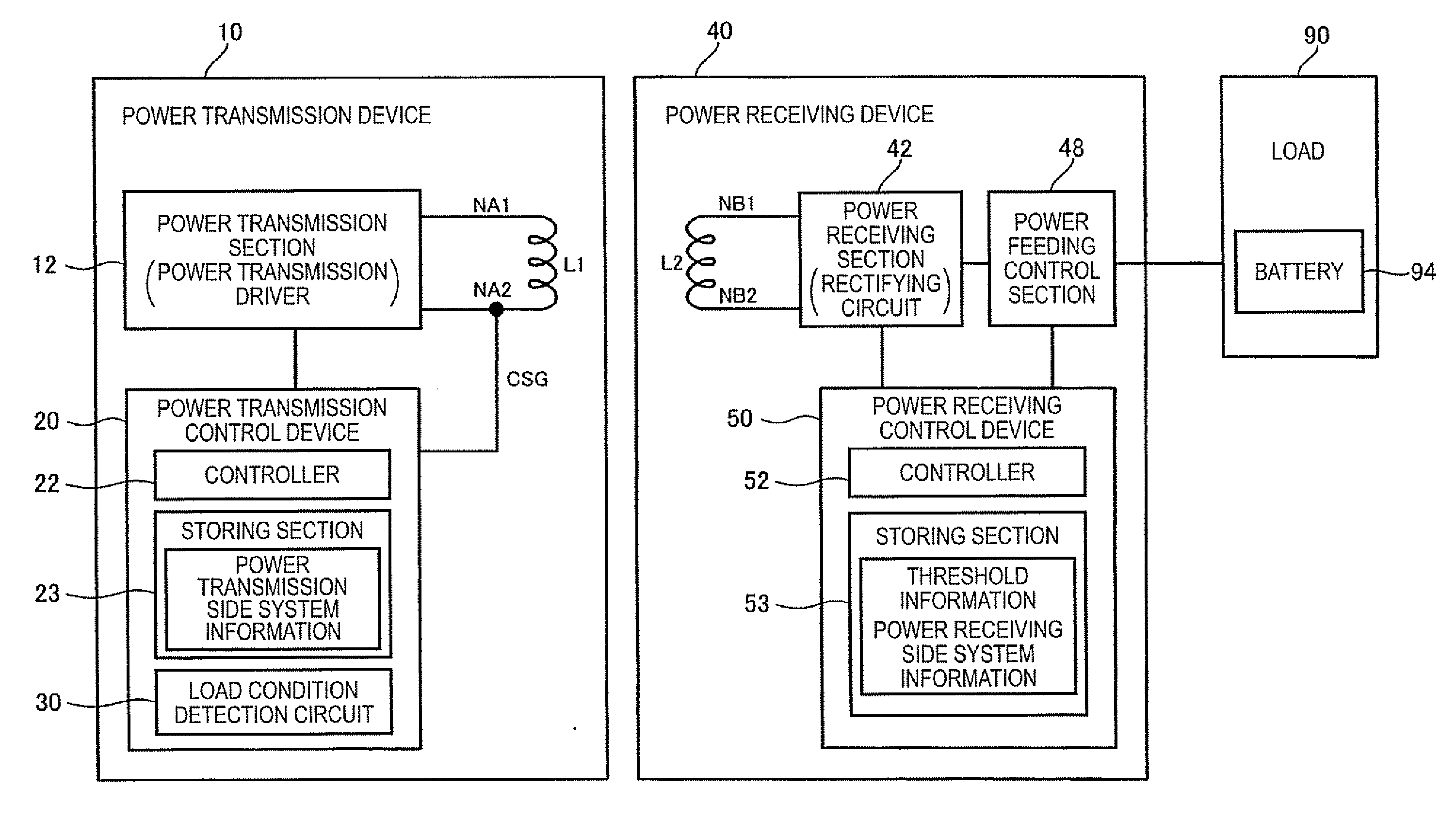
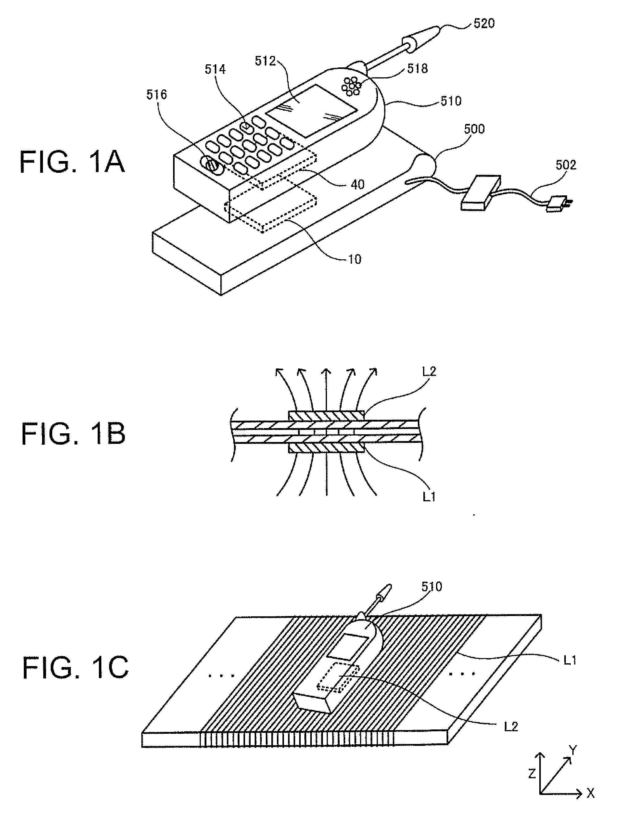
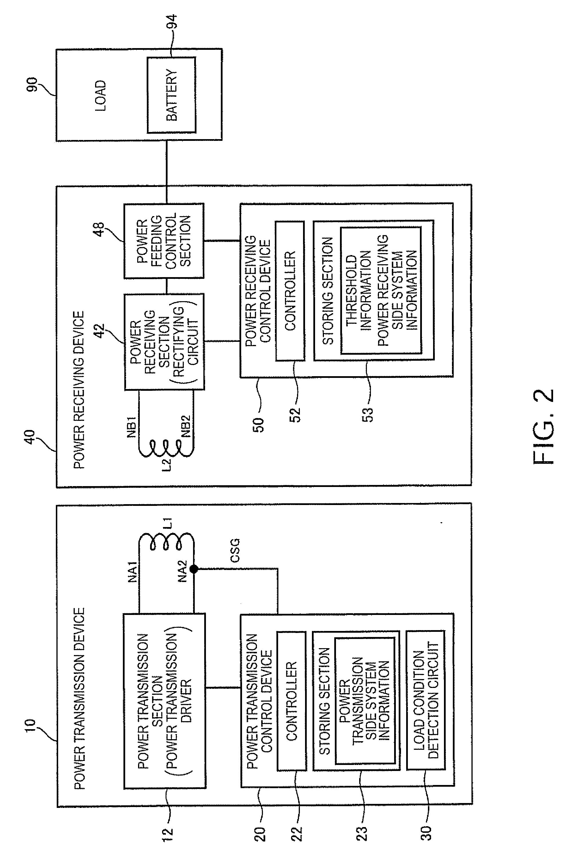
[0060]FIG. 1A shows an example of an electronic apparatus employing a contactless power transmission method according to an embodiment of the invention. A charger 500 (a cradle) that is one of electronic apparatuses includes a power transmission device 10. A cell phone 510 that is one of electronic apparatuses includes a power receiving device 40. The cell phone 510 includes a display 512 such as an LCD, an operation section 514 composed of buttons and the like, a microphone 516 (a voice input section), a speaker 518 (a voice output section), and an antenna 520.

[0061]Power is supplied to the charger 500 through an AC adapter 502, and the power is transmitted from th...


PUM


Abstract

A power transmission control device included in a contactless power transmission system in which power is transmitted from a power transmission device to a power receiving device by electromagnetically coupling a primary coil and a secondary coil and the power is supplied to a load of the power receiving device, includes a controller controlling the power transmission control device, and a load condition detection circuit detecting a load condition on a power receiving side. The controller determines the load condition on the power receiving side based on threshold information received from the power receiving device and load condition detection information from the load condition detection circuit.

Description

[0001]This application claims priority to JP 2008-165988 filed in Japan on Jun. 25, 2008, the entire disclosures of which is hereby incorporated by reference in its entirety.BACKGROUND[0002]1. Technical Field[0003]The present invention relates to a power transmission control device, a power transmission device, a power receiving control device, a power receiving device, and an electronic apparatus.[0004]2. Related Art[0005]In recent years, contactless power transmission (non-contact power transmission) has been highlighted. The contactless power transmission makes it possible to perform transmission of electric power by utilizing electromagnetic induction without using a metallic contact. As an example of the contactless power transmission, charging cell phones and household equipment (e.g., cordless handsets of telephones) are suggested.[0006]JP-A-2006-60909 is a first example of related art of the contactless power transmission. In the first example, an ID authentication is realiz...

Claims


Application Information

Patent Timeline
IPC IPC(8): H02J7/02H02J7/00
CPCH02J9/005H02J7/025H02J7/00045H02J7/0044H02J50/80H02J50/90H02J50/12H02J50/60
Inventor KAMIJO, TAKAHIROKONDO, YOICHIROONISHI, KOTAKAMIYAMA, MASAYUKISHIOZAKI, NOBUTAKA
Owner SAMSUNG ELECTRONICS CO LTD
Why Eureka
Try Eureka