Magnetic component

a technology of magnetic components and components, applied in the field of magnetic components, can solve the problems of increasing the size of the coil and the problem of conventional coils, and achieve the effect of reducing the width of the coil, improving the quality factor and the resistance loss of the coil

Inactive Publication Date: 2009-12-31
DELTA ELECTRONICS INC
View PDF8 Cites 26 Cited by
  • Summary
  • Abstract
  • Description
  • Claims
  • Application Information

AI Technical Summary

Benefits of technology

[0007]In view of the foregoing problem, the present invention is to provide a magnetic component for the inductor, transformer or filter with the high-quality factor and high performance.
[0008]The present is also to provide a magnetic component for providing proper quality factor and performance according to the actual need.
[0010]In the above-mentioned magnetic component of the present invention, the thickness of the wire is gradually increased or decreased from the inner circle to the outer circle of the wire.
[0022]In the magnetic component of the present invention, the quality factor and the coil resistance loss thereof can be easily improved by gradually increasing or decreasing the thickness of the coil, gradually increasing and then gradually decreasing the width of the coil, gradually decreasing and then gradually increasing the width of the coil, gradually increasing and then gradually decreasing the gap between adjacent two circles of the coil, or gradually decreasing and then gradually increasing the gap between adjacent two circles of the coil. Thus, the performance of the magnetic component of the present invention can be enhanced. Furthermore, the quality factor of the magnetic component can be adjusted to a proper status by the combination of the above-mentioned embodiments, so that the performance of the magnetic component can reach the optimum.

Problems solved by technology

This will cause the increase of the coil size.
Thus, the conventional coil has become a problem for the present minimized devices.

Method used


Image

  • Magnetic component
  • Magnetic component
  • Magnetic component

Examples


Embodiment Construction

[0033]The present invention will be apparent from the following detailed description, which proceeds with reference to the accompanying drawings, wherein the same references relate to the same elements.

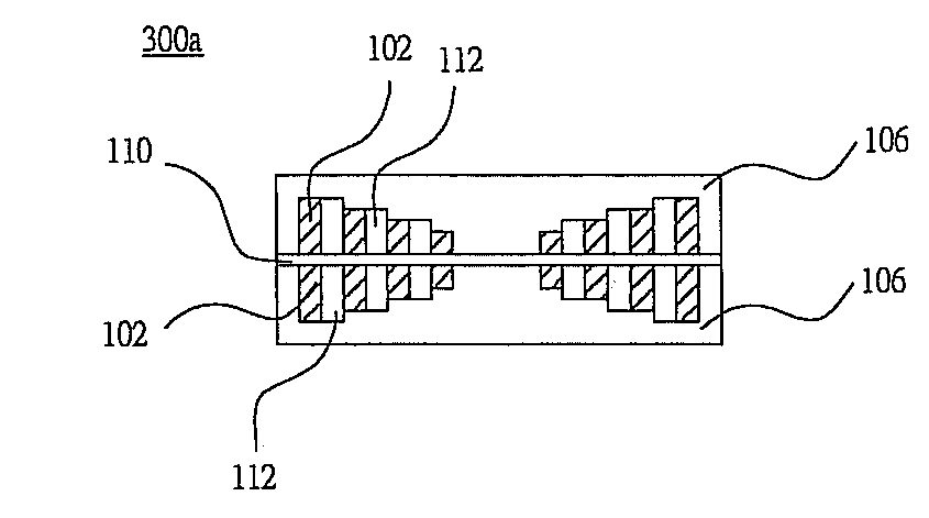
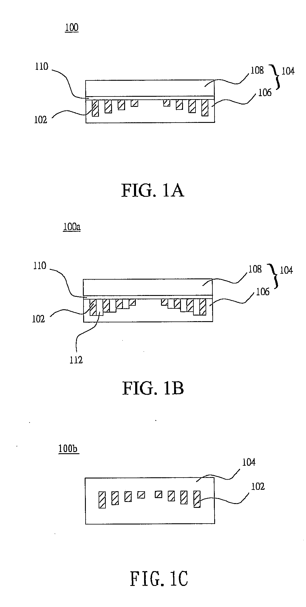
[0034]FIG. 1A is a sectional view of a magnetic component 100 according to a preferred embodiment of the present invention. The magnetic component 100 includes at least one coil 102 and a permeable structure 104. The magnetic component 100 can be an inductor, a transformer, a common mode noise filter or a differential mode noise filter. In addition, the magnetic component can be applied to a DC / DC converter or a radio frequency (RF) module.

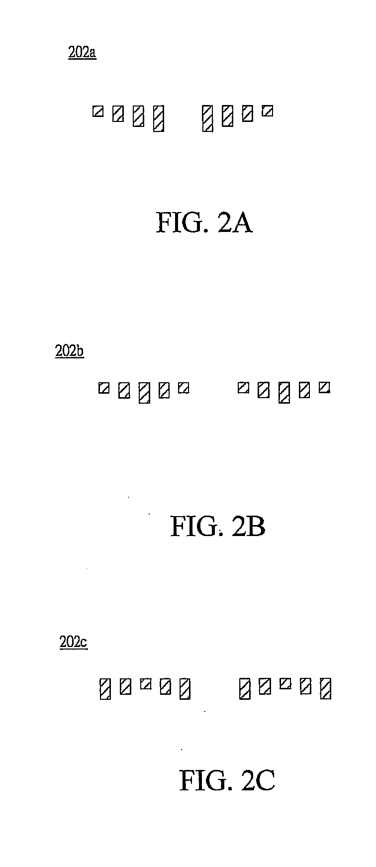
[0035]The coil 102 is formed by a radially wound wire, and the thickness of an inner circle of the wire near a center axis of the coil 102 is different from that of an outer circle of the wire near a surface of the coil 102. More specifically, the thickness of the wire is various depending on the distance from a portion of the wire to the center axi...


PUM

PropertyMeasurementUnit
magneticaaaaaaaaaa
thicknessaaaaaaaaaa
permeableaaaaaaaaaa

Abstract

A magnetic component includes at least one coil and a permeable structure. The coil is formed by a radially wound wire, and the thickness of the wire is various according to the distance from a portion of the wire to the center axis of the coil. The coil is covered by the permeable structure.

Description

CROSS REFERENCE TO RELATED APPLICATIONS[0001]This Non-provisional application claims priority under 35 U.S.C. §119(a) on Patent Application No(s). 097124509 filed in Taiwan, Republic of China on Jun. 30, 2008, the entire contents of which are hereby incorporated by reference.BACKGROUND OF THE INVENTION[0002]1. Field of Invention[0003]The present invention relates to a magnetic component and, in particular, to a magnetic component with the high-quality factor and high performance.[0004]2. Related Art[0005]The present magnetic component has been widely applied to the inductor, transformer or noise filter in the power converter. The loss of the magnetic component is mainly caused by the coil loss and the core loss. Regarding to the power inductor or transformer, the resistance loss power caused by the current flowing through the coil and the resistance of the coil have the relationship of direct proportion.[0006]Since the thickness, the width and the gap between two adjacent circles of...

Claims


Application Information

Patent Timeline
Patent Type & Authority Applications(United States)
IPC IPC(8): H01F5/00
CPCH01F17/0006H01F17/04H01F2017/0073H01F41/046H01F27/323
Inventor LEE, CHENG-CHANGZHOU, DENG-YANLU, ZENG-YILIN, MING-HSIENCHANG, HENG-CHUNGCHEN, WEISHING, TAI-KANG
Owner DELTA ELECTRONICS INC
Why Eureka
Try Eureka