Analytical Instrument Having Internal Reference Channel

Inactive Publication Date: 2009-12-31
REICHERT
View PDF18 Cites 19 Cited by
  • Summary
  • Abstract
  • Description
  • Claims
  • Application Information

AI Technical Summary

Benefits of technology

[0011]It is therefore an object of the present invention to improve accurac

Problems solved by technology

In any given instrument, there is a tendency for signal drift over time due to temperature and light source variations.
This introduces slight variations from measurement to measurement because the coupling fluid layer may not have a uniform thickness for each measurement, such that the sensor slide may be slightly

Method used


Image

  • Analytical Instrument Having Internal Reference Channel
  • Analytical Instrument Having Internal Reference Channel
  • Analytical Instrument Having Internal Reference Channel

Examples


Example

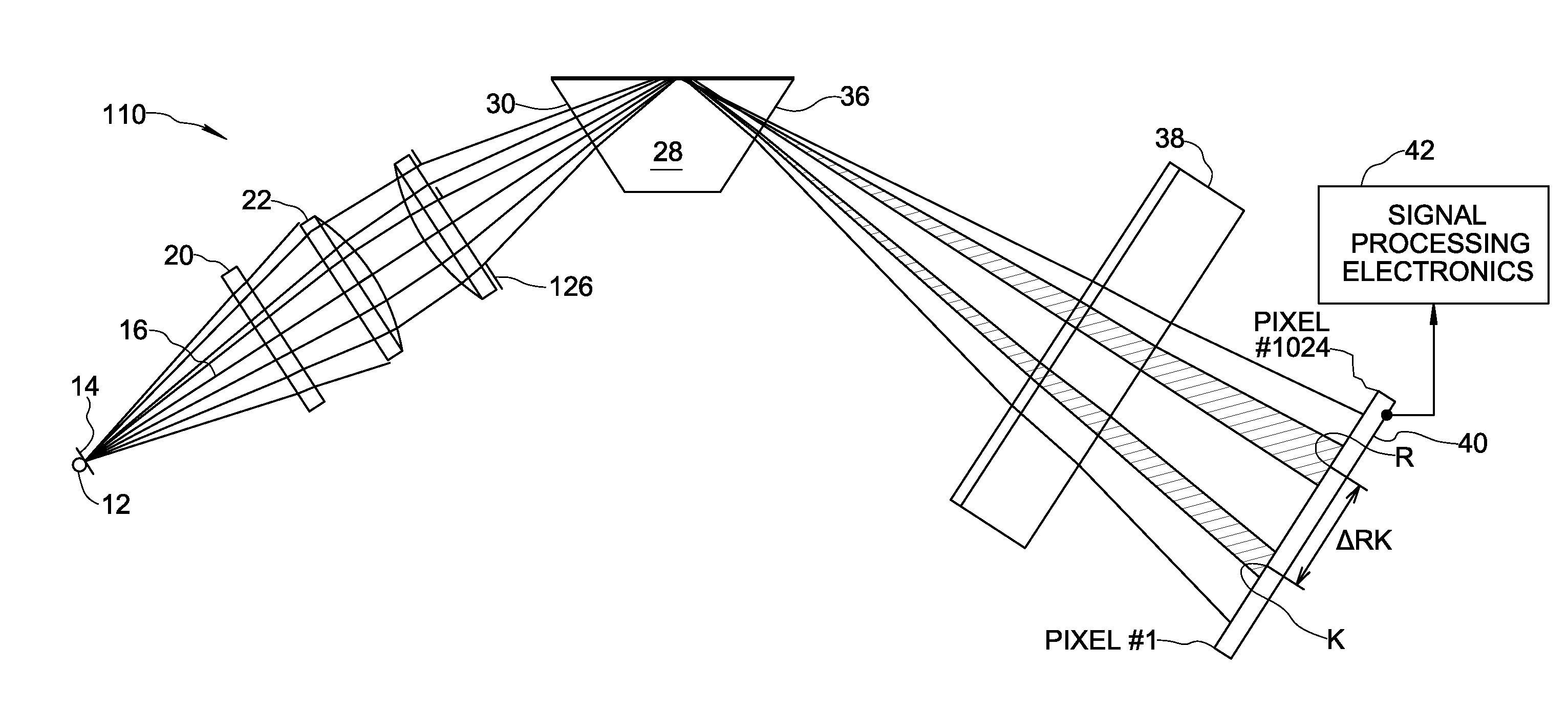
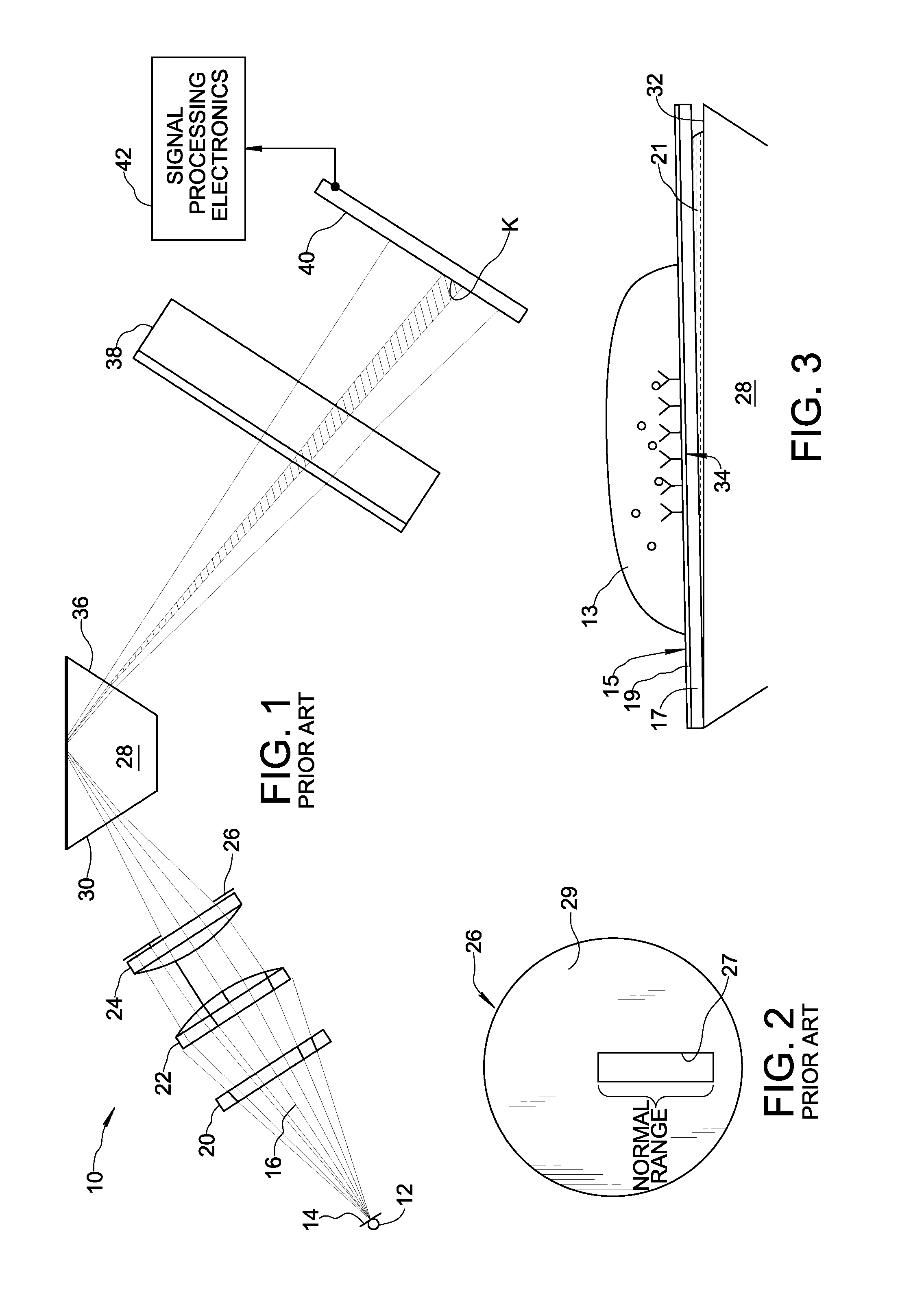
[0032]Reference is made initially to FIGS. 1-3 for description of an analytical instrument 10 formed in accordance with the prior art. Analytical instrument 10 comprises a light source 12 illuminating a pinhole aperture 14 for generating an illumination beam 16 propagating along an optical path. Instrument 10 further comprises a polarizer 20 located in the optical path for polarizing illumination beam 16. The polarized illumination beam 16 then passes through a pair of focusing lenses 22, 24 and is thereby converted from a divergent beam to a convergent beam. A diaphragm 26 is positioned in optical path 18 immediately after the second focusing lens 24 to act as a field stop. As shown in FIG. 2, diaphragm 26 includes a single elongated slit aperture 27 surrounded by an opaque region 29. Light transmitted through aperture 27 of diaphragm 26 is received by high-index prism 28 through a light entry surface 30 of the prism. The convergent illumination beam 16 may be focused at a point ju...


PUM


Abstract

An analytical instrument for making measurements based on detection of an SPR resonance minimum or a refractometer transition shadowline on a detector array is improved by configuring a diaphragm of the instruments illumination system to include a first aperture, a second aperture, and an opaque region between the first and second apertures, wherein the opaque region of the diaphragm casts a shadow on the detector array to provide a reference minimum from which a relative location of the resonance minimum or transition shadowline is measurable. By establishing a reference minimum on the detector array as a reference location for relative measurement, the instrument compensates for signal drift and other instrument variations. The diaphragm may include additional apertures and opaque regions for generating additional reference minima over the extent of the detector array.

Description

FIELD OF THE INVENTION[0001]The present invention relates to analytical instruments for optically measuring a parameter of a test sample by analyzing detector signal information provided by pixels of a light-sensitive detector array, wherein the measurement value depends upon a location of a defining feature of light received by the detector array. The present invention may be applied, for example, to analytical instruments for measuring molecular binding interactions using the principle of surface plasmon resonance (SPR), wherein the defining feature is a resonance minimum (resonance shadow) cast on the detector array. As a further example, the present invention may be applied to critical angle refractometers, wherein the defining feature is a transition “shadowline” between an illuminated region and a darkened region on the detector array.BACKGROUND OF THE INVENTION[0002]Snell's law describes what happens when light is directed through a high refractive index prism (e.g. Sapphire—...

Claims


Application Information

Patent Timeline
IPC IPC(8): G01N21/55
CPCG01N21/553
Inventor LUBER, EDWARD J.HOOVER, DOUGLAS H.
Owner REICHERT
Why Eureka
Try Eureka