[0012]As noted above, when the automobile is in motion, the passing air tends to depress the spray, and so the inventors recognized that higher
nozzle operating pressures were needed. Also, for the windshield washing systems using high-performance fluidic
nozzle assemblies, it was observed that
efficacy of
headlamp cleaning depended on the nozzle pressure, thus calling for a pump with an improved Pressure-flow rate (P-Q) curve, as compared to the prior art. Also, as noted above, in
cold weather, the washer
fluid viscosity increases and pump pressures reduce. With reduced
pump pressure, it was observed that nozzles operated at lower pressure in
cold weather, leading to less effective spray onto the headlamp or windshield and reduced cleaning action for the washing
system. It was, therefore, a priority to improve this aspect of the pump, i.e. a better pump P-Q curve at higher viscosities (up to 25 cP).
[0013]The washer pump
assembly of the present invention provides excellent P-O performance at normal operating temperatures and considerably better P-Q performance in the cold, when compared to typical or prior art washer pumps. The enhanced P-Q performance and other improvements are the result of a newly developed impeller and casing, which together form the impeller casing
assembly.
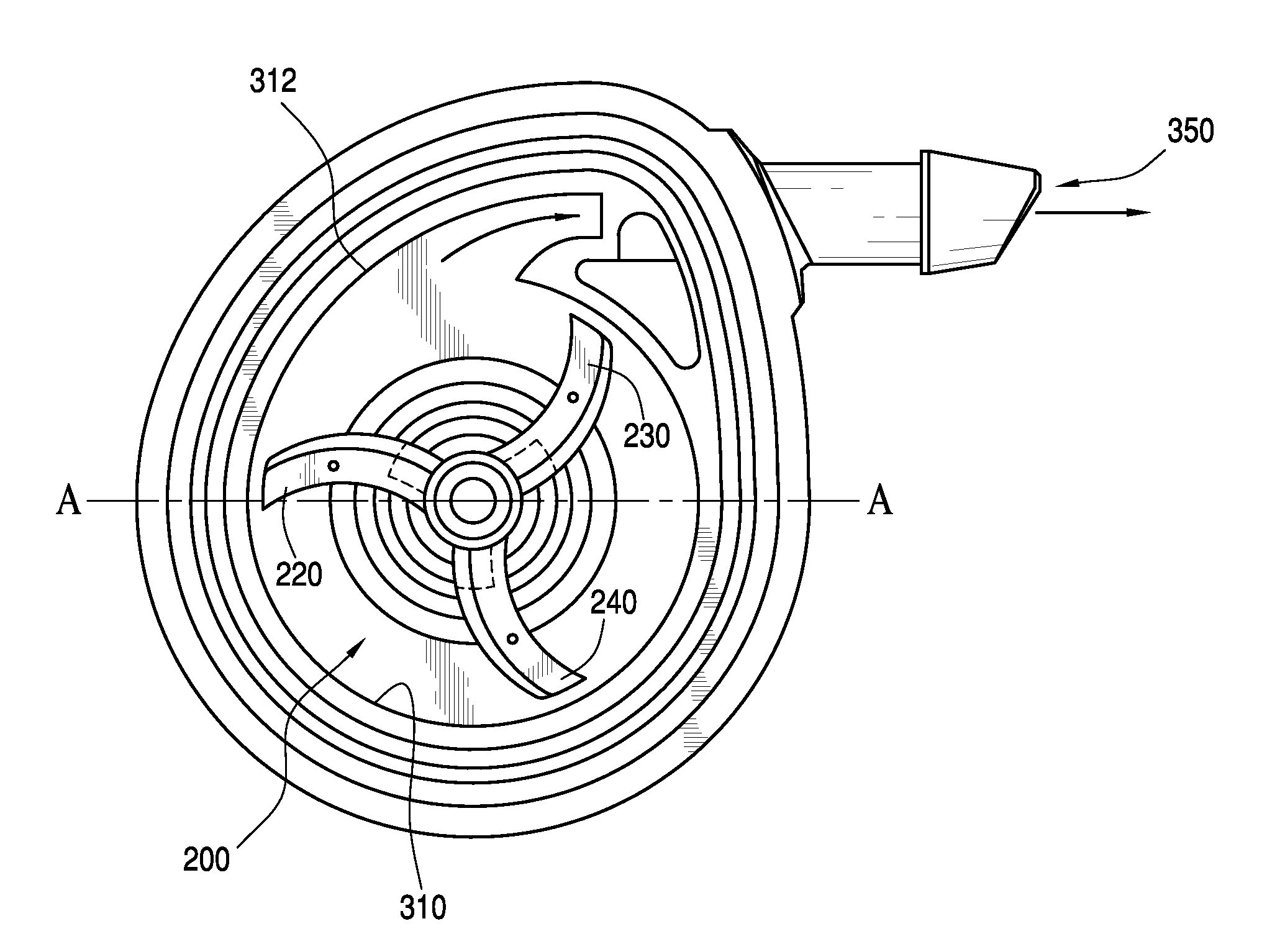
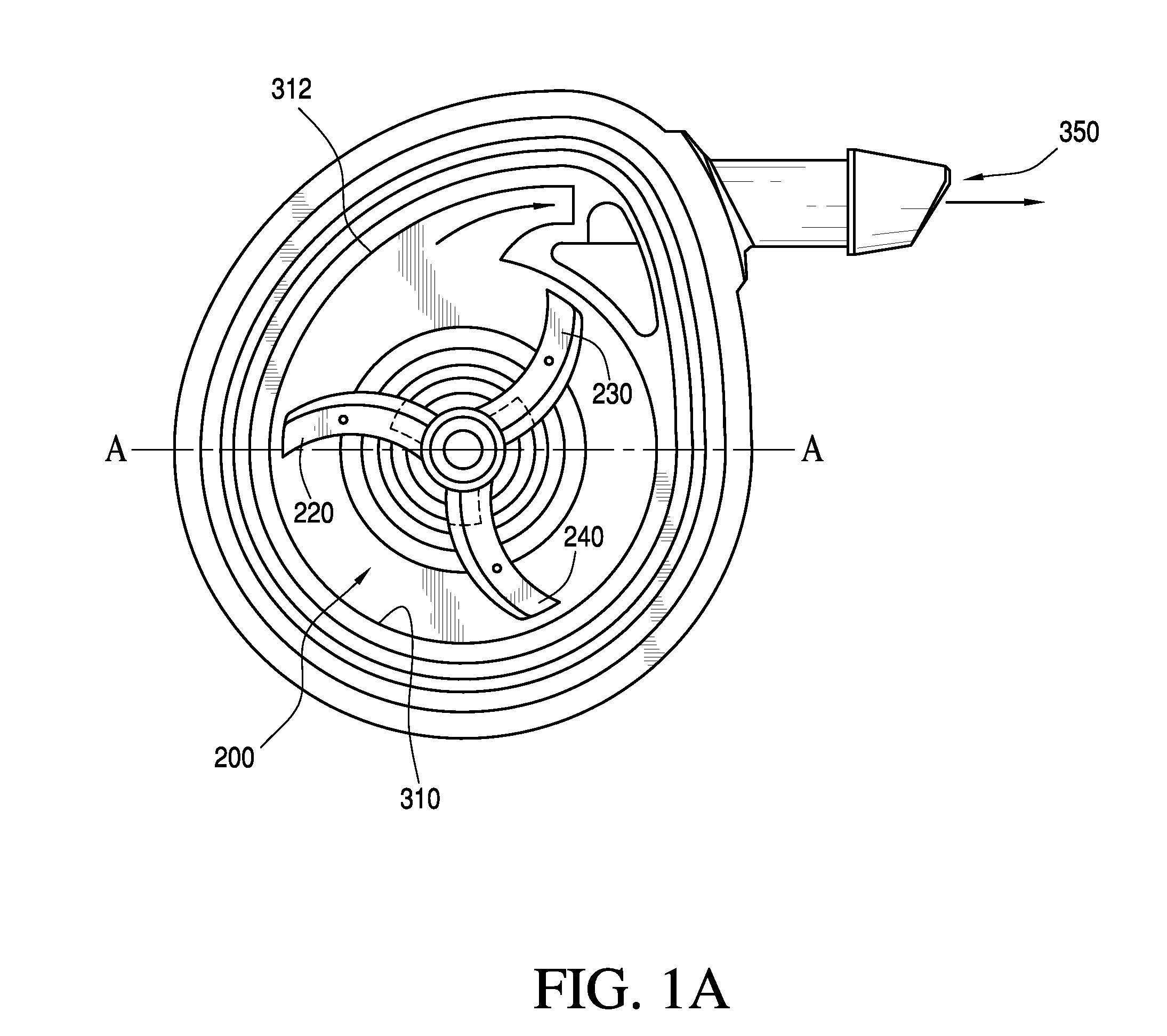
[0015]The casing of the pump has a slight spiral deviation from the basic circular style that most existing automotive
centrifugal pump casings have. The impeller of the present invention, when combined with the present invention's spiral-shaped casing contributes to enhanced P-Q performance, especially for cold performance. When seen in plan view, the present invention's casing has a circular profile for most of a circle (e.g., approx. 260 degrees, providing constant clearance with the impeller) and then has a gradually radial sidewall
diameter for increasing impeller clearance all the way to the pump's fluid outlet or exit, where the casing's radial sidewall
radius is 1.6 times the
radius of the segment having the circular profile.
[0016]In view of present invention's potential to be the basis for better pumps, the inventors have measured and benchmarked many leading brands and pumps and identified their performance characteristics. An extensive facility for testing and developing new pumps permitted development of many prototypes and assemblies. The P-Q curves of the pump or the present invention was compared to an existing high performance pump (by VDO™), and
room temperature performance was evaluated along with cold performance, and significant improvements in cold performance were observed over the VDO pump. At
room temperature this invention yields a 1.5 PSI performance
advantage. In
ethanol water mixtures at −4 F (25 cP), this invention outperforms the prior art washer pumps by 6-8 PSI. All of these pressure advantages are accomplished with less current [energy] consumption. This indicates the higher efficiency of this pump assembly.
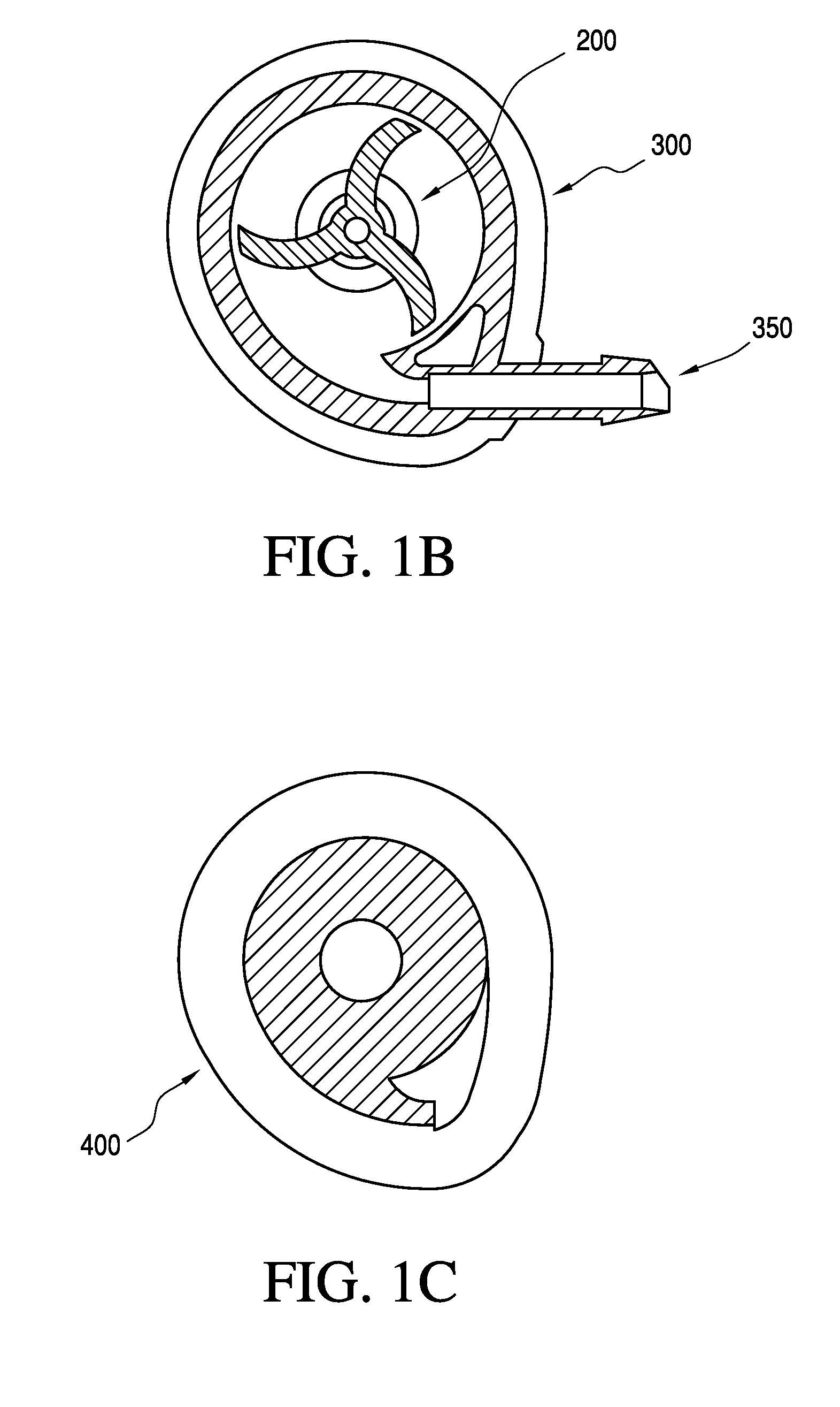
[0020]Generally speaking, the pump assembly of the present invention has a few characteristics that are common to all of the exemplary configurations. The enhanced pump assembly includes an impeller and
volute casing designed to provide high operating pressures (“P”) and flow rates (“Q”) with low energy usage. The impeller has a central shaft carrying radially projecting curved primary vanes, and each primary vane also has a twist in the radial direction. Secondary impeller vanes define triangular connecting fillet-like wall segments connecting each primary vane to the impeller shaft. The secondary vanes can also have a twist angle similar to the primary vanes. The casing of the pump has a slight spiral deviation so that the
pump chamber's radial sidewall flares away from the swept area of the impeller's vanes to define a fluid outlet that contributes to higher P-Q performance, especially when pumping colder fluids. The casing has a circular profile for approx. 260 deg (providing constant clearance with impeller) and then, approaching the outlet, transitions to a gradually increasing clearance all the way to the exit, where the casing
radius is 1.6 times the radius of the casing sidewall's circular profile.

