Degradation assessment system for power storage device, vehicle, degradation assessment method for power storage device, and computer-readable recording medium having program recorded thereon for computer to execute the degradation assessment method

a technology for power storage devices and degradation assessment methods, which is applied in the direction of electric devices, propulsion using engine-driven generators, process and machine control, etc., can solve the problem of not adequately assessing the degradation state of secondary batteries

Inactive Publication Date: 2009-12-31
TOYOTA JIDOSHA KK
View PDF34 Cites 41 Cited by
  • Summary
  • Abstract
  • Description
  • Claims
  • Application Information

AI Technical Summary

Benefits of technology

[0008]Another object of the present invention is to provide a degradation assessment system and a vehicle capable of appropriately indicating to a user the degradation state of a power storage device mounted on the vehicle.
[0009]Still another object of the present invention is to provide a degradation assessment method with which the degradation state of a power storage device mounted on a vehicle can be reliably assessed, and a computer-readable recording medium having a program recorded thereon for a computer to execute the degradation assessment method.
[0010]A further object of the present invention is to provide a degradation assessment method with which the degradation state of a power storage device mounted on a vehicle can be appropriately indicated to a user, and a computer-readable recording medium having a program recorded thereon for a computer to execute the degradation assessment method.

Problems solved by technology

Therefore, the degradation determination device disclosed in the above-referenced publication may not adequately assess the degradation state of the secondary battery.

Method used


Image

  • Degradation assessment system for power storage device, vehicle, degradation assessment method for power storage device, and computer-readable recording medium having program recorded thereon for computer to execute the degradation assessment method
  • Degradation assessment system for power storage device, vehicle, degradation assessment method for power storage device, and computer-readable recording medium having program recorded thereon for computer to execute the degradation assessment method
  • Degradation assessment system for power storage device, vehicle, degradation assessment method for power storage device, and computer-readable recording medium having program recorded thereon for computer to execute the degradation assessment method

Examples


first embodiment

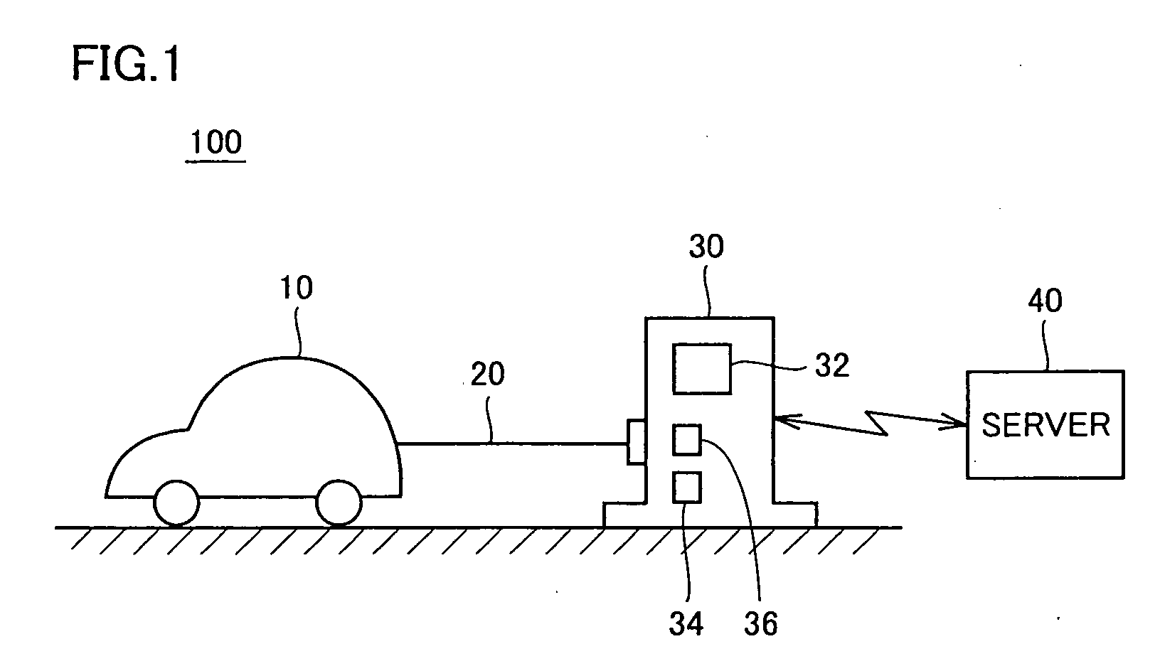
[0061]FIG. 1 is an overall view of a degradation assessment system according to a first embodiment of the present invention. Referring to FIG. 1, degradation assessment system 100 includes a vehicle 10, a charge station 30 and a server 40.

[0062]Vehicle 10 is an electrically-driven vehicle mounted with a power storage device and a motor each serving as a source for supplying power, and is configured for example as an electric vehicle or hybrid vehicle. The following description of the first embodiment is applied particularly to a hybrid vehicle in which the power storage device is charged and discharged frequently. Vehicle 10 can be connected by a connection cable 20 to charge station 30, and the power storage device can be charged with electric power supplied from charge station 30 as described hereinlater.

[0063]Connection cable 20 is an electric power line for supplying a charging electric power from charge station 30 to vehicle 10. Further, connection cable 20 is used as a data co...

second embodiment

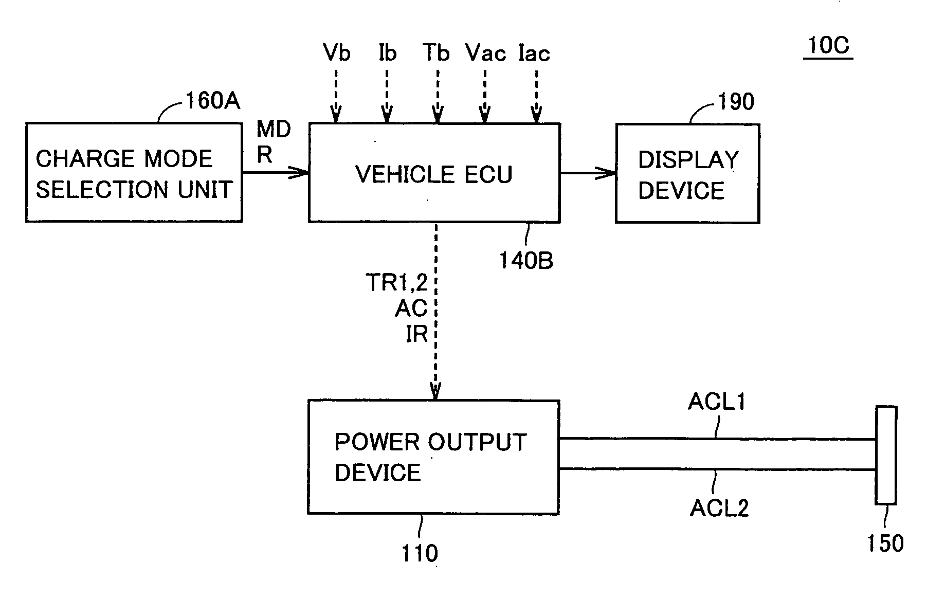
[0130]According to a second embodiment, a user can select a charge mode when power storage device B is charged from charge station 30, based on the result of assessment of the degradation indicated to the user. Specifically, the user can select a quick charge mode in which power storage device B is charged at a maximum charge rate, or a low-rate charge mode in which power storage device B is charged at a low charge rate with which progression of degradation of power storage device B can be suppressed.

[0131]FIG. 15 is a schematic configuration diagram of a vehicle 10A according to the second embodiment. Referring to FIG. 15, vehicle 10A includes a charge mode selection unit 160 in addition to the components of vehicle 10 in the first embodiment shown in FIG. 5. Charge mode selection unit 160 is an input device for allowing a user to select the maximum charge mode or low-rate charge mode when power storage device B is charged from charge station 30.

[0132]When charge mode selection uni...

third embodiment

[0135]According to the first embodiment and its modifications as well as the second embodiment, the degradation state of power storage device B is assessed at charge station 30. According to a third embodiment, the assessment is carried out all on the vehicle side.

[0136]FIG. 16 is a schematic configuration diagram of a vehicle in the third embodiment. Referring to FIG. 16, as compared with the components of vehicle 10 in the first embodiment shown in FIG. 5, vehicle 10B does not include modem 130 and includes a vehicle ECU 140A instead of vehicle ECU 140.

[0137]Vehicle ECU 140A collects data about voltage Vb, charging current Ib and temperature Tb of power storage device B and collects data about voltage Vac between electric power lines ACL1, ACL2 and current Iac flowing through electric power lines ACL1, ACL2, when power storage device B in power output device 110 is charged from charge station 30 connected to connector 150. Vehicle ECU 140A uses the collected data to assess the deg...


PUM


Abstract

A degradation assessment system includes a vehicle mounted with a power storage device, a charge station, a connection cable for connecting the vehicle to the charge station, and a server. The vehicle can charge the power storage device from the charge station. The charge station includes a degradation assessment device. The degradation assessment device collects data such as the voltage, charging current and temperature of the power storage device when the power storage device is charged from the charge station, and uses the collected data and assessment data obtained from the server to assess the degradation state of the power storage device.

Description

TECHNICAL FIELD[0001]The present invention relates to a technique for assessing a degradation state of a power storage device mounted on a vehicle.BACKGROUND ART[0002]Japanese Patent Laying-Open No. 2004-014403 discloses a degradation determination device for a secondary battery. The degradation determination device includes load history estimation means for estimating a history of a load on a secondary battery based on the electric current flowing in the secondary battery, and degradation determination means for making a determination as to degradation of the secondary battery based on the terminal voltage of the secondary battery, when the current flowing in the secondary battery changes from a charge state or discharge state to approximately zero and when the load history estimated by the load history estimation means is within a range that can be regarded as a predetermined history.[0003]The degradation determination device makes a determination as to degradation of the secondar...

Claims


Application Information

Patent Timeline
Patent Type & Authority Applications(United States)
IPC IPC(8): G01R31/36H02J7/00B60L3/00B60L50/16B60R16/04
CPCG01R31/3679G01R31/007B60L2240/545B60L2240/547B60L2240/549B60L2250/16Y02T90/14Y04S30/12Y04S30/14G01R31/392B60L53/14B60L53/22B60L50/61B60L50/16B60L53/24B60L53/665B60L58/16B60L53/18B60L53/305Y02T10/62Y02T10/70Y02T10/7072Y02T90/12Y02T90/167Y02T90/16
Inventor UCHIDA, MASATOSHI
Owner TOYOTA JIDOSHA KK
Why Eureka
Try Eureka