Die casting machine and die casting method

a die casting machine and die casting technology, applied in the direction of mold control devices, manufacturing tools,foundry moulding apparatus, etc., can solve the problems of insufficient molten metal, no longer possible production, and each proposal has a problem, so as to achieve fast injection molding, fast speed value, and fast speed.

Inactive Publication Date: 2010-01-07
UBE MASCH CORP LTD
View PDF0 Cites 19 Cited by
  • Summary
  • Abstract
  • Description
  • Claims
  • Application Information

AI Technical Summary

Benefits of technology

[0052]In particular, in the die casting method or die casting machine capable of fast injection molding, by properly selecting a combination of a plurality of gas bottles, a fast speed raising is achieved in a brief time under high pressure at start time by utilizing pressure drop of hydraulic oil in the accumulator due to the expansion of gas without performing complicated control, the fast speed value is reduced by spontaneous reduction in speed due to the fluid resistance of the molten metal in the mold, the pressure is reduced to an optimum value before the completion of filling, and thus the impact value at the time of completion of filling is relaxed and the fast injection molding is enabled, and at the same time, the occurrence of surge pressure of molten aluminum in the cavity of the mold is suppressed and the occurrence of burr and spouting of molten metal, or scattering of tip of molten metal, etc., are prevented.
[0053]Further, even if there are variations in the amount of supply of molten metal, the plunger is reduced in speed spontaneously before the position of the completion of filling due to the fluid resistance of the molten metal that has flowed into the mold, and therefore, the position of reduction in speed in the mold is the same and thus the occurrence of surge pressure is suppressed and the occurrence of burr and spouting of molten metal, or scattering of tip of molten metal etc., are prevented.
[0054]The symbols in the parenthesis attached to each means indicate the relationship of correspondence with specific means in embodiments, which will be described later.
[0055]The present invention may be more fully understood from the description of the preferred embodiments of the invention set forth below, together with the accompanying drawings.

Problems solved by technology

Even more so, spouting of molten metal occurs, and either way, there arises a problem that “continuation of production is no longer possible”.
However, each proposal has a problem.
On the other hand, if the amount of molten metal within the sleeve 7 is small, breaking is activated before molten metal is sufficiently distributed in the mold cavity (the breaking timing is advanced relatively), and therefore, a defect that molten metal is insufficient may occur.
However, the following problem occurs.
If power at a fast filling step is reduced, the fast pressure-raising time is lengthened, and therefore, there arises a problem that a fast peed cannot be obtained.
Further, in the molding test under this condition (9 MPa), a significant burr still occurs.
However, if the pressure is further reduced, the pressure-raising time is lengthened and the fast speed is reduced and the defect in the run of molten metal (misrun: molten metal does not reach any part in the cavity) occurs, and therefore, this condition is a compromise one in the actual molding test.
As for the condition of 9 MPa, if the fast pressure-raising and the fast (high) speed operation are not affected, it is necessary to reduce the fast injection output to remove the burr and with this method to reduce pressure (i.e., power), no satisfactory molding result could be obtained in the molding test.
Then, if filling is completed without any action taken, the pressure of molten metal in the cavity sharply increases (surge pressure occurs) when the filling is completed and the mold opens, spouting of molten metal occurs, and a very dangerous state where a molding operation is no longer possible is brought about.
A machine having a fast speed of 10 m / sec or more as specifications at a no-load injection step is referred to as an ultrafast machine, and molding by an ultrafast machine has a difficult problem.
The problem is that a high precision is required for the amount of molten metal to be supplied by a molten metal supplier and if the amount of molten metal is excessive, filling is completed before the speed is reduced sufficiently and a surge pressure occurs, and if the amount of molten metal is insufficient, scattering (or splash) of tip of molten metal occurs, discontinuous filling results, and the defect of cold shut occurs, and what is worse, gas inclusion defect occurs.
However, it is very difficult to improve the precision of molten metal supply of a supplier and a method for solving the problem is hard to find.
As described above, the position at the time of completion varies depending on the amount of molten metal, and therefore, there arises a problem that surge pressure occurs or scattering of tip of molten metal occurs.
On the other hand, it is difficult to improve the precision of molten metal supply of a supplier and also to grasp the amount of molten metal, and therefore, it is also difficult to adjust the position at which reduction in speed is commenced by grasping the amount of molten metal.
There has been made another proposal (refer to patent document 1), however, with this proposal, it is not possible to suppress the occurrence of surge pressure and defect of product quality because an error is produced at the position of the commencement of reduction in speed of the injection rod when there are variations in the amount of molten metal stored in the plunger sleeve as described above.[Patent document 1] Japanese Unexamined Patent Publication (Kokai) No. 2001-300714[Patent document 2] Japanese Unexamined Patent Publication (Kokai) No. 2004-216432

Method used


Image

  • Die casting machine and die casting method
  • Die casting machine and die casting method
  • Die casting machine and die casting method

Examples


first embodiment

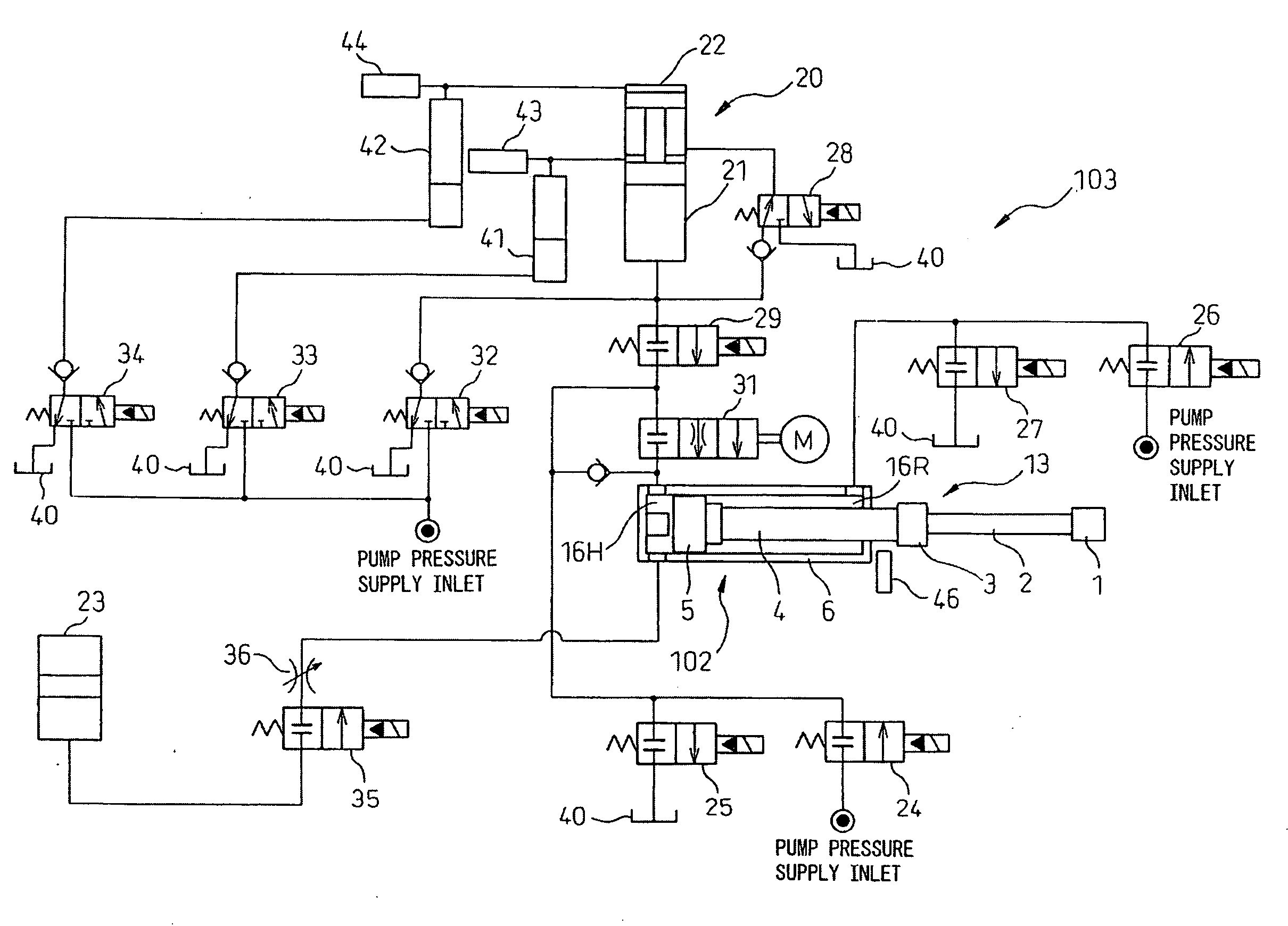
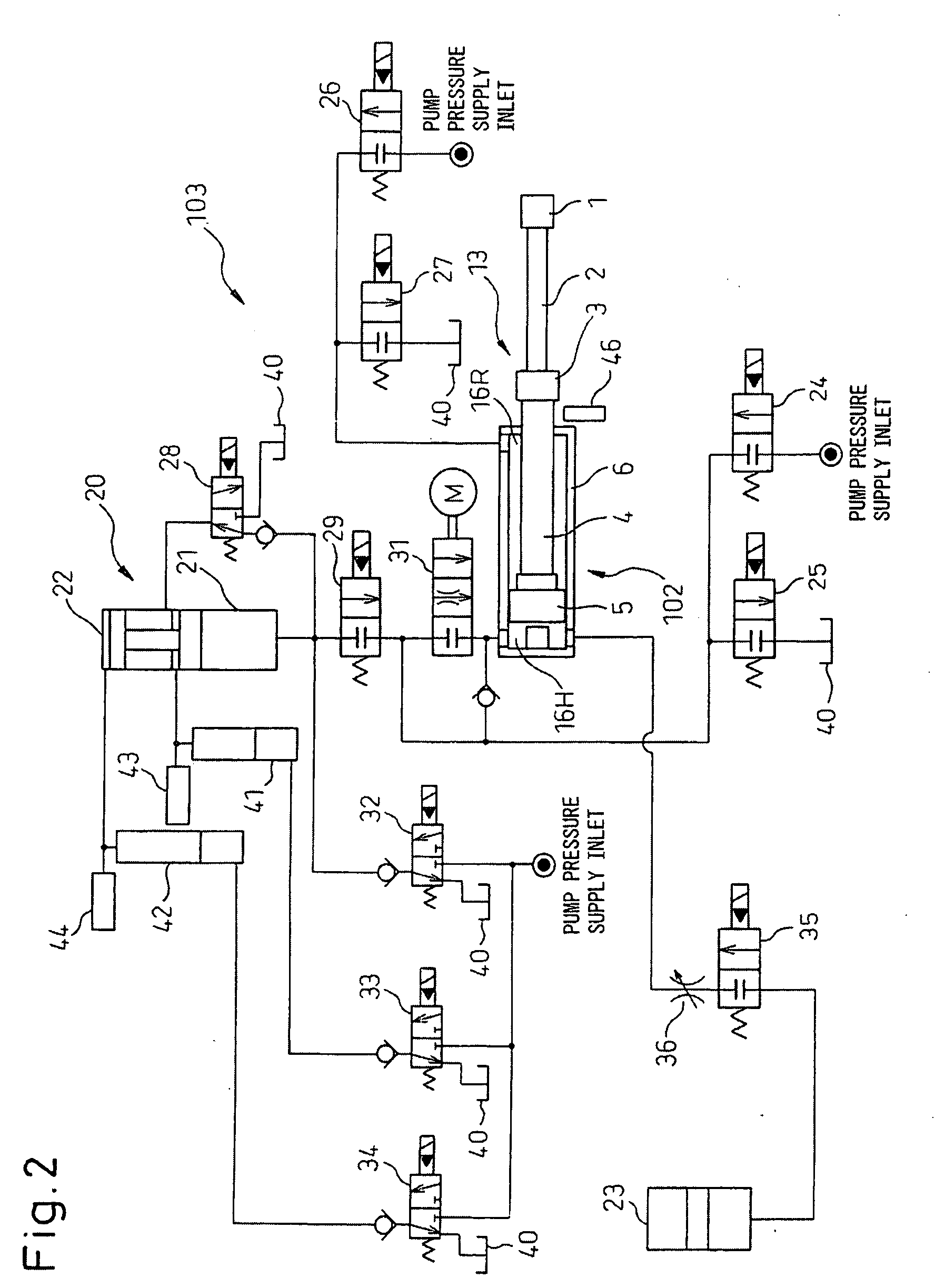
[0087]FIG. 2 illustratively shows the hydraulic circuit of a hydraulic device 103 in the present invention, which drives the injection cylinder 102. On the line on the inlet side of a head chamber 16H of the cylinder 6, a seventh valve 31 that controls the injection speed and the piston ACC (accumulator) 20 capable of discharging oil at a high flow rate for fast (high-speed) injection are provided, and in the present embodiment, that the piston ACC (accumulator) 20 has a preferred configuration is one of the characteristics. The piston ACC 20 is divided into two parts, that is, an upper part and a lower part, and a piston 221 in a fast pressure-raising piston ACC (accumulator)-B 22 at the upper part has a projection part 222 of a rod part and the projection part 222 presses the upper surface of a piston 211 of an injection piston ACC (accumulator)-A 21 at the lower part. In the fast pressure-raising piston ACC-B 22 at the upper part, a high-pressure gas (for example, 14 MPa) is accu...

third embodiment

[0108]FIG. 16 illustratively shows a hydraulic circuit of a hydraulic device 303 in the present invention, which drives the injection cylinder 102. On a connection inlet line to the head chamber 16H of the cylinder 6, the injection piston accumulator (ACC) 20 is provided so as to communicate fluidly therewith, which is capable of discharging at a high flow rate for fast injection via the fast speed adjusting valve (the seventh valve) 31 that controls the injection speed. In general, the cylindrical injection piston accumulator 20 is partitioned into two chambers by the piston 211 that slides and reciprocates in the piston accumulator 20, one of them is the hydraulic chamber 218 in which hydraulic oil is stored and the other is the gas chamber 217 in which gas is stored. The gas chamber 217 is provided with high-pressure gas from a gas bottle to press under pressure the piston 211 to supply the hydraulic oil in the hydraulic oil chamber to the hydraulic circuit of the hydraulic devic...

fourth embodiment

[0122]FIG. 24 is a chart representing the change of the injection speed, the injection pressure (pressure in the head chamber 16H of the injection cylinder 102), etc. with respect to the time progress, and the state of the piston rod, each valve, etc., at that time in the FIG. 14 is basically the same as FIG. 23 and the symbols etc. are the same as those in FIG. 23. The first, second, and third switching valves 75, 76, 77 in FIG. 23 do not exist in FIG. 24, and instead, the time chart of the filling force pattern adjusting valve 82 is shown. It is known from FIG. 24 that the filling force pattern adjusting valve 82 is maintained at a fixed valve opening degree after molding is started.

[0123]Next, the effects and working of the above-mentioned embodiments are explained. According to the die casting machine in the first embodiment of the present invention, the following effects can be expected.

[0124]In particular, in the die casting method or the die casting machine capable of fast i...


PUM

PropertyMeasurementUnit
pressureaaaaaaaaaa
pressureaaaaaaaaaa
speedaaaaaaaaaa

Abstract

A die casting machine that suppresses the occurrence of surge pressure, prevents the occurrence of burrs and spouting of molten metal, and further minimizes variations in the quality of a molded product on site.
The die casting machine comprises a mold (101) that cast-molds a product, an injection cylinder (102) for injecting molten metal (15) to the mold, and a hydraulic device (103) for pressing under high pressure the injection cylinder. The hydraulic device comprises a piston ACC (20) that supplies hydraulic oil to press under pressure a piston (13) of the injection cylinder (102) and an injection cylinder inlet valve (31). The piston ACC comprises a high pressure fast pressure-raising piston accumulator (22, 322) and a low-pressure injection piston accumulator (21, 321).

Description

CROSS-REFERENCE TO RELATED APPLICATIONS[0001]The present invention claims patent based on the priority of Japanese Patent Application No. 2006-290165 filed on Oct. 25, 2006 and Japanese Patent Application No. 2007-229335 filed on Sep. 4, 2007 and these contents are incorporated herein as reference and continued in the subject application.BACKGROUND OF THE INVENTION[0002]1. Field of the Invention[0003]The present invention relates to a die casting machine and a die casting method and, more particularly, to a fast (high-speed) injection metal die casting machine and a die casting method.[0004]2. Description of the Related Art[0005]A die casting method and a die casting machine using a light metal material, such as aluminum, for molding are widely used in various fields, such as the automobile industry and die casting manufacturing. In the die casting method, a product having a predetermined shape is molded by pumping under pressure molten metal supplied into a plunger sleeve through a...

Claims


Application Information

Patent Timeline
Patent Type & Authority Applications(United States)
IPC IPC(8): B22D17/00B22D17/20B22D17/32
CPCB22D17/32B22D17/203
Inventor UCHIDA, MASASHIHIRAIZUMI, KAZUKIOKAZAKI, YOSHINORI
Owner UBE MASCH CORP LTD
Why Eureka
Try Eureka