
Thermally activated variable stiffness composites for aircraft seals

a composite material and variable stiffness technology, applied in the field of aircraft components, can solve the problems of contradictory stiffness and deformation requirements, limited vertical clearance on hangar decks, and aircraft may have additional hinges to fold the wing tips, so as to reduce the gap in the apparatus, the effect of changing stiffness and variable stiffness

Active Publication Date: 2010-01-07
THE BOEING CO
View PDF4 Cites 21 Cited by
  • Summary
  • Abstract
  • Description
  • Claims
  • Application Information

AI Technical Summary

Benefits of technology

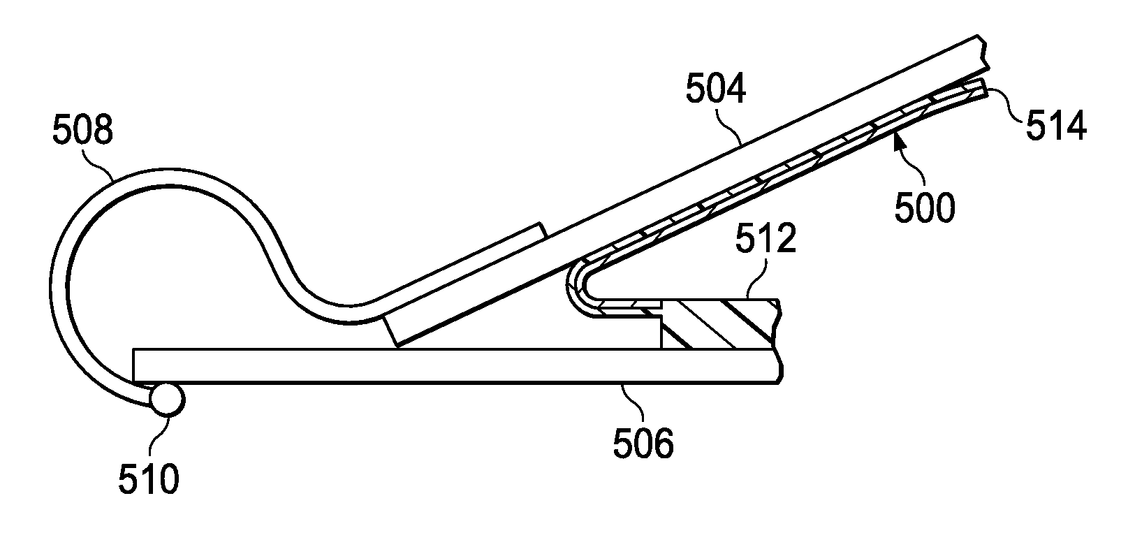
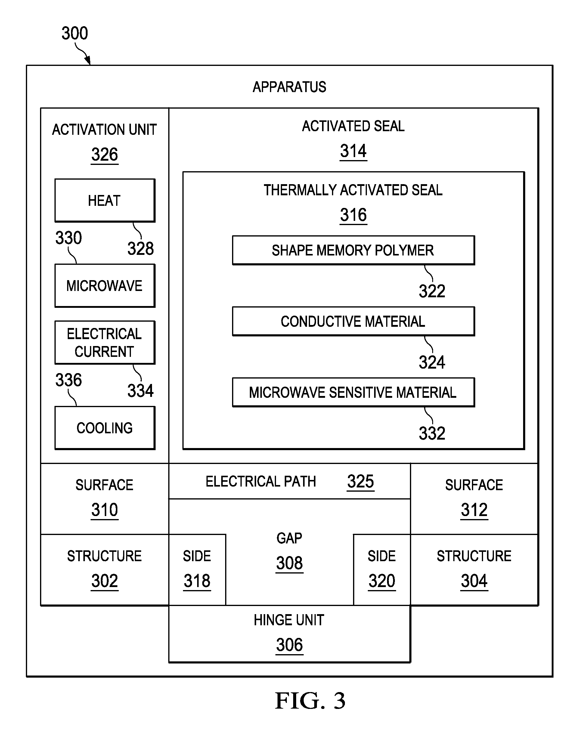
[0012]In another advantageous embodiment, an aircraft comprises a fuselage, an outboard wing structure, an inboard wing structure, a hinge unit, a thermally activated seal, and an activation unit. The hinge unit is capable of allowing the outboard wing structure to move relative to the inboard wing structure between a deployed position and a stowed position. The thermally activated seal is attached to at least one of the outboard wing structure and the inboard wing structure. The thermally activated seal has a variable stiffness that may be changed in response to a change in a temperature in the thermally activated seal such that the thermally activated seal is capable of changing stiffness and being deformed when the outboard wing structure is moved between the deployed position and the stowed position. The activation unit is capable of applying heat to the thermally activated seal to change the temperature of the thermally activated seal to a selected temperature at which the thermally activated seal is substantially compliant.
[0013]In yet another advantageous embodiment, a method is present for reducing gaps in an apparatus. A temperature of a thermally activated seal is changed to change a stiffness of the thermally activated seal from a substantially stiff state to a substantially compliant state, wherein the thermally activated seal is attached to at least one of a first structure and a second structure in the apparatus. At least one of the first structure and the second structure is moved while the thermally activated seal is in the substantially compliant state such that a gap between the first structure and the second structure in the apparatus is reduced.

Problems solved by technology

In some cases, vertical clearance may be limited on hangar decks in an aircraft carrier.
With this type of limit, some aircraft may have additional hinges to fold the wing tips downwards.
Additionally, this type of seal also may permit electrical conductivity and impedance continuity across the gap for low observable properties.
The contradictory stiffness and deformation requirements may be difficult to balance in a manner that prevents physical gap formation and allows for electrical continuity in the seal.

Method used


Image

  • Thermally activated variable stiffness composites for aircraft seals
  • Thermally activated variable stiffness composites for aircraft seals
  • Thermally activated variable stiffness composites for aircraft seals

Examples


Embodiment Construction

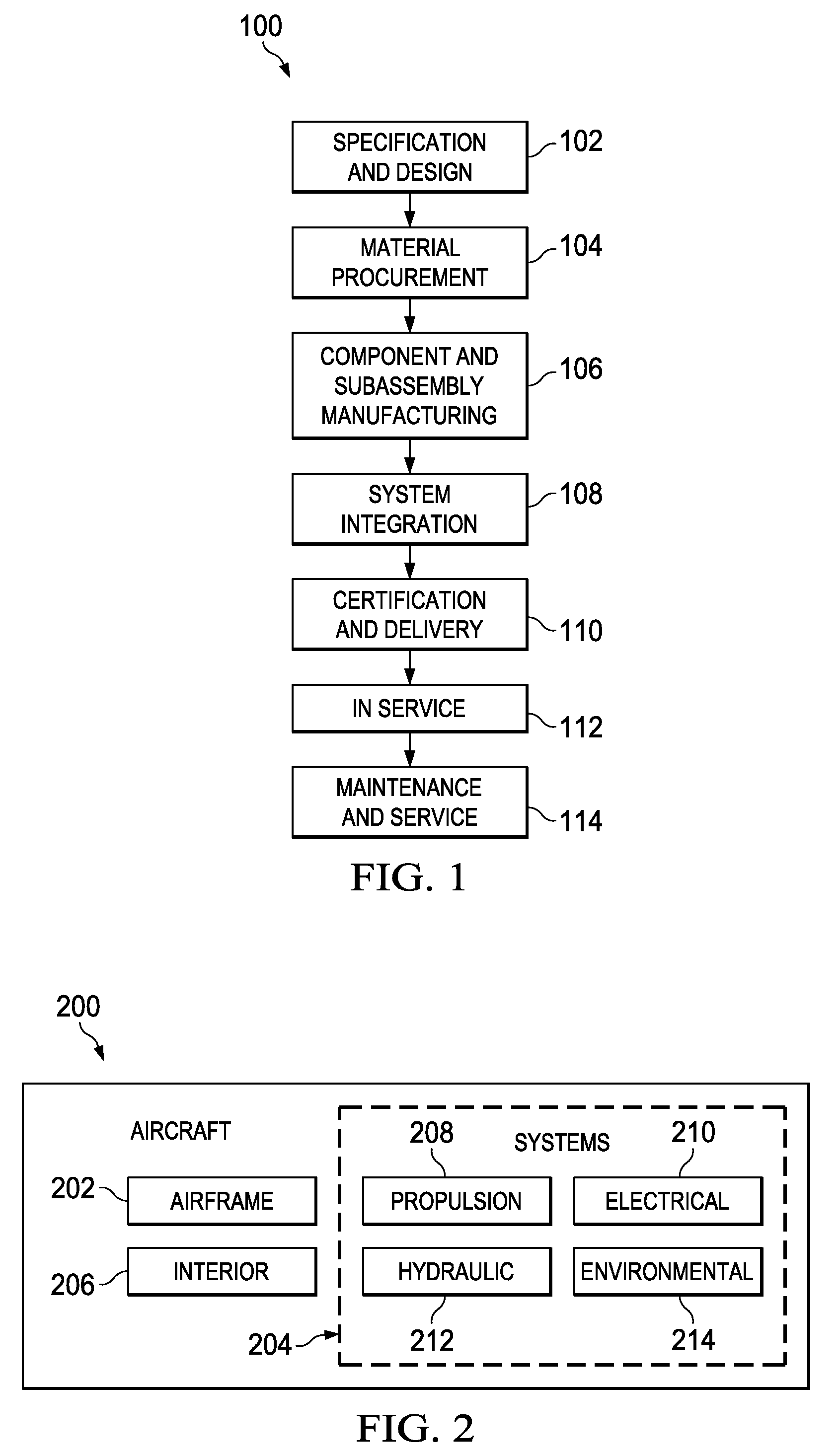
[0044]Referring more particularly to the drawings, embodiments of the disclosure may be described in the context of the aircraft manufacturing and service method 100 as shown in FIG. 1 and aircraft 200 as shown in FIG. 2. Turning first to FIG. 1, a diagram illustrating an aircraft manufacturing and service method is depicted in accordance with an advantageous embodiment.

[0045]During pre-production, exemplary aircraft manufacturing and service method 100 may include specification and design 102 of aircraft 200 in FIG. 2 and material procurement 104. During production, component and subassembly manufacturing 106 and system integration 108 of aircraft 200 in FIG. 2 takes place. Thereafter, aircraft 200 in FIG. 2 may go through certification and delivery 110 in order to be placed in service 112. While in service by a customer, aircraft 200 in FIG. 2 is scheduled for routine maintenance and service 114, which may include modification, reconfiguration, refurbishment, and other maintenance...


PUM

PropertyMeasurementUnit
stiffnessaaaaaaaaaa
temperatureaaaaaaaaaa
shape memoryaaaaaaaaaa

Abstract

An apparatus has a first structure, a second structure, and an activated seal. The second structure has a first position adjacent to the first structure such that the first structure is not in contact with the second structure. The activated seal is attached to at least one of the first structure and the second structure. The activated seal has a variable stiffness that may be changed in response to a stimuli such that the activated seal is capable of being deformed when at least one of the first structure and the second structure are moved relative to each other.

Description

BACKGROUND INFORMATION[0001]1. Field[0002]The present disclosure relates generally to aircraft components and in particular to thermally activated variable stiffness composite materials used in aircraft components. Still more particularly, the present disclosure relates to a method and apparatus for using thermally activated variable stiffness composite materials in seals for aircraft.[0003]2. Background[0004]In aircraft, a folding wing is a design feature that may be used to save space. For example, naval based aircraft that operate from limited deck space on an aircraft carrier may have folding wings to reduce the amount of space occupied by the aircraft. A folding wing allows an aircraft to occupy less space in a confined hangar because the folded wing normally rises over the fuselage.[0005]This folded configuration decreases the floor area occupied by the aircraft. In some cases, vertical clearance may be limited on hangar decks in an aircraft carrier. With this type of limit, s...

Claims


Application Information

Patent Timeline
Patent Type & Authority Applications(United States)
IPC IPC(8): H05B6/64B64C1/06
CPCY02T50/145B64C3/56Y02T50/10
Inventor HENRY, CHRISTOPHER P.MCKNIGHT, GEOFFREY P.HERRERA, GUILLERMO A.DOTY, ROBERT E.CLEMONS, RICHARD LEEDROUIN,, JR., DONALD V.
Owner THE BOEING CO
Learn More