Alternator

a permanent magnet alternator and alternator technology, applied in the field of alternators, can solve the problems of low electrical energy output in comparison to mechanical energy input, adverse effects on the efficiency of permanent magnet alternators, and relative poor efficiency

Inactive Publication Date: 2010-01-07
WIND CONCEPTS
View PDF11 Cites 21 Cited by
  • Summary
  • Abstract
  • Description
  • Claims
  • Application Information

AI Technical Summary

Benefits of technology

[0038]In a still further embodiment of the alternator according to the invention, high impedance bleeding resistors prevent voltage spikes in any unused or out of circuit coil plates.

Problems solved by technology

However, a problem with the permanent magnet alternators described above is they have a relatively poor efficiency, that is, the electrical energy output is low in comparison to the mechanical energy input.
The efficiency of the permanent magnet alternator is thus adversely affected.
The permanent magnet alternators described above are also limited when the speed of the drive shaft is constant, in that only one pre-determined voltage output can be produced.

Method used


Image

  • Alternator
  • Alternator
  • Alternator

Examples


Embodiment Construction

[0049]The invention will be further illustrated by the following description of embodiments thereof, given by way of example only with reference to the accompanying drawings.

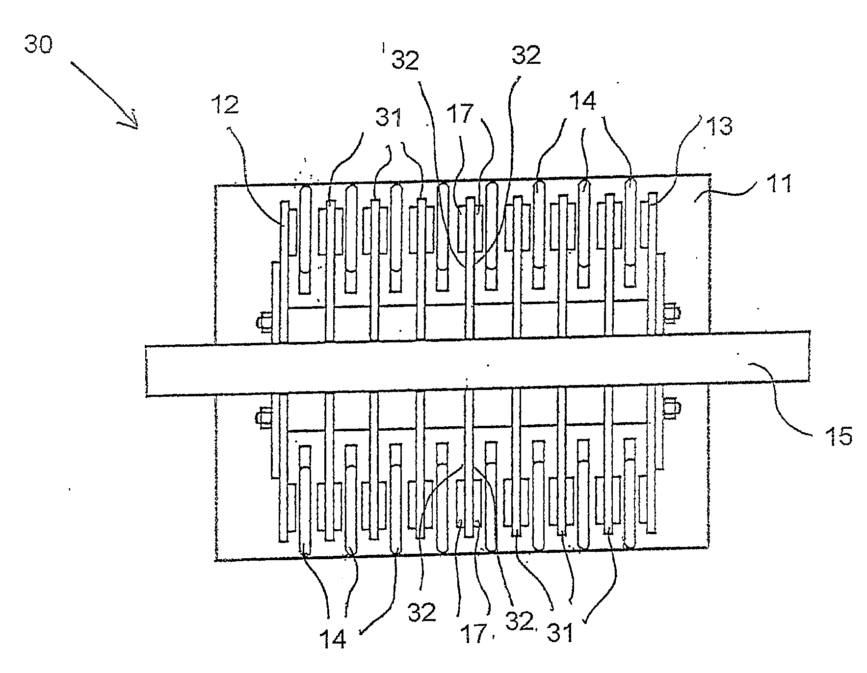
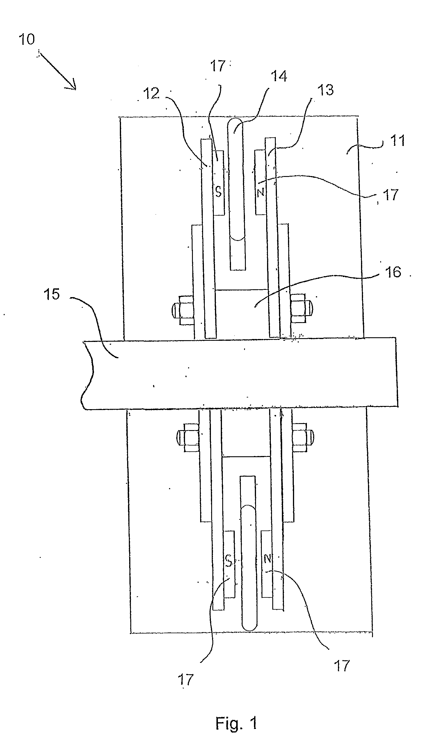
[0050]Referring to FIG. 1, there is indicated, generally at 10, an alternator, in accordance with the invention, the alternator 10 comprising a housing 11, a pair of opposed magnet end plates 12, 13 mounted within housing 11, a coil plate 14 mounted in and held in position within the housing 11, between the pair of magnet end plates 12, 13. A drive shaft 15 is located within the housing 11 and is coupled to the pair of magnet end plates 12, 13. A spacer 16, on the drive shaft 15, maintains a set distance between the pair of magnet end plates 12, 13.

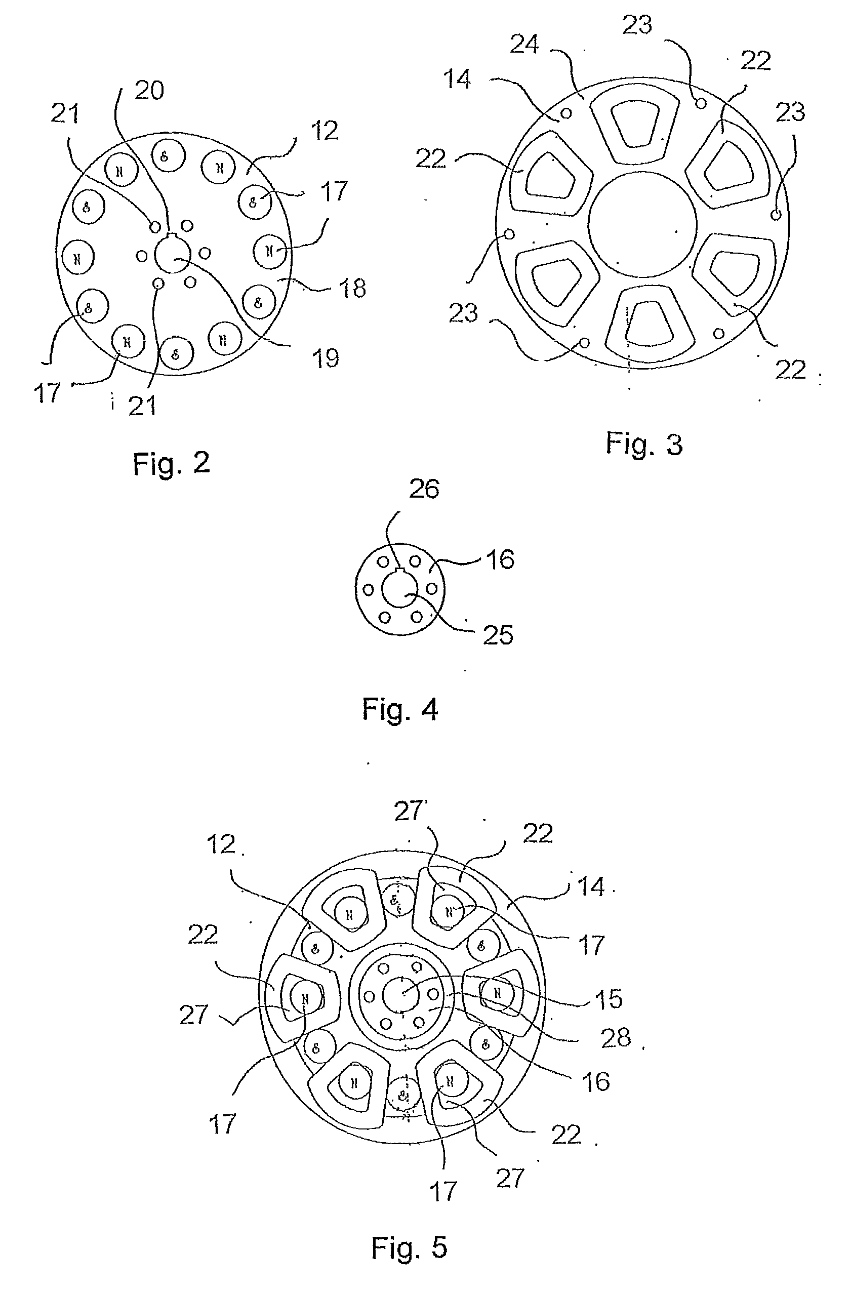
[0051]Each magnet end plate 12, 13 has a plurality of permanent magnets 17 disposed thereon. Each magnet 17 on the opposed magnet end plate 12 is aligned with a magnet 17 of opposite polarity on the other magnet end plate 13.

[0052]Referring to FIG. 2, the magnet end p...


PUM


Abstract

An alternator (10) has a housing (11), a pair of opposed magnet end plates (12, 13) mounted within the housing (11) a coil plate (14) mounted in and held in position within the housing (11), between the pair of magnet end plates (12, 13). A drive shaft (15) is located within housing (11) and is coupled to the pair of magnet end plates (12, 13). Each magnet end plate (12, 13) has a plurality of permanent magnets (17) disposed thereon. The coil plate (14) has a plurality of magnet wire coils (not shown) embedded therewithin such that they can be seen from both sides of the coil plate (14). In use, turning of the drive shaft (15) causes the magnet end plates (12, 13) to move relative to the coil plate (14) thus exciting each magnet wire coil (not shown) on each side resulting in the generation of an alternating current therein.

Description

TECHNICAL FIELD[0001]This invention relates to an alternator and, in particular, to a permanent magnet alternator for converting mechanical energy to alternating current electrical energy.BACKGROUND ART[0002]Current permanent magnet alternators typically comprise a rotor or drive shaft, a magnet rotor assembly mounted for rotation on the rotor or drive shaft and a stationary stator with magnet wire coils disposed in the stationary stator. When a magnetic field flux is moved relative to a stationary electrical conductor such as copper wire, or vice versa, the magnetic field flux will induce an electromotive force (EMF) or voltage in the electrical conductor. If the conductor is connected to an electrical load, then current will flow. The magnet rotor assembly of current permanent magnet alternators rotates relative to the stationary stator and alternating current is generated in the magnet wire coils of the stationary stator. The magnet wire coils of the stationary stator are connect...

Claims


Application Information

Patent Timeline
Patent Type & Authority Applications(United States)
IPC IPC(8): F03D9/00H02K21/24H02K11/04H02P9/48
CPCH02K21/24H02K16/00H02K21/14
Inventor JEFFERSON, JOHN LESLIE
Owner WIND CONCEPTS
Why Eureka
Try Eureka